
KeithNewby
Members
-
Joined
-
Last visited
-
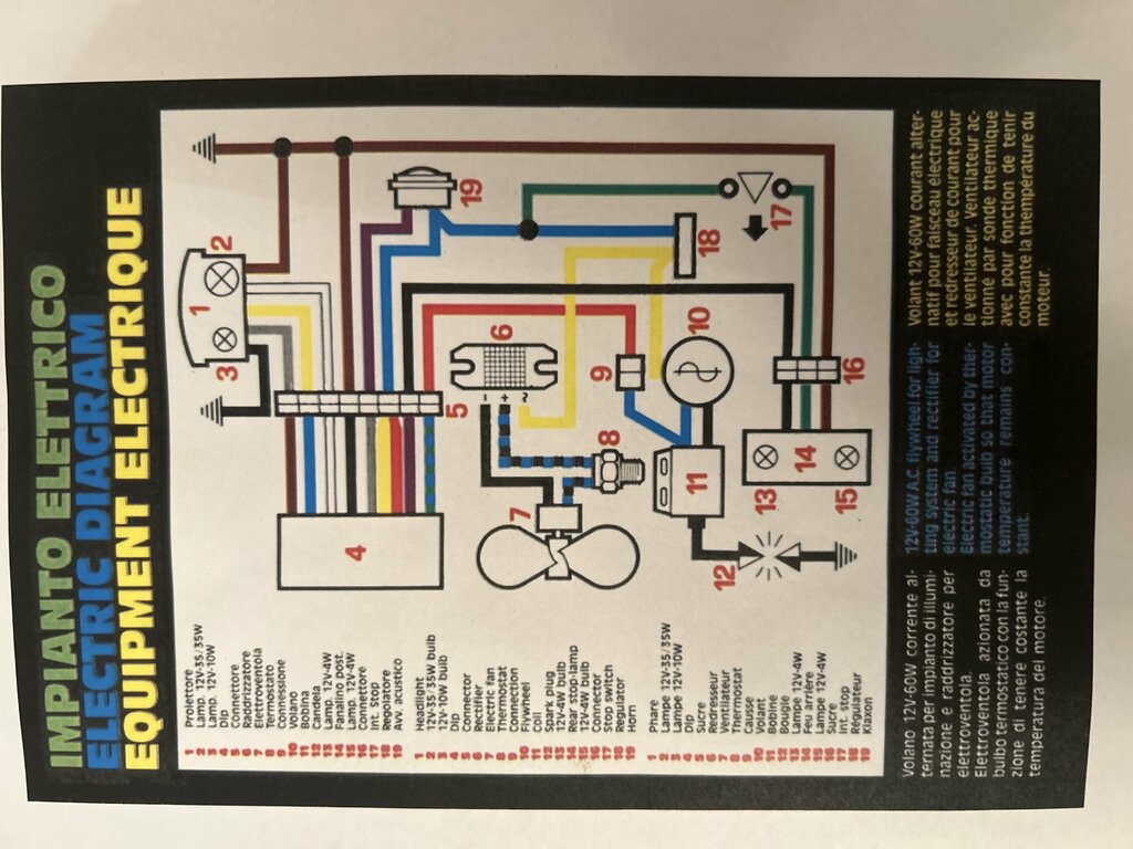
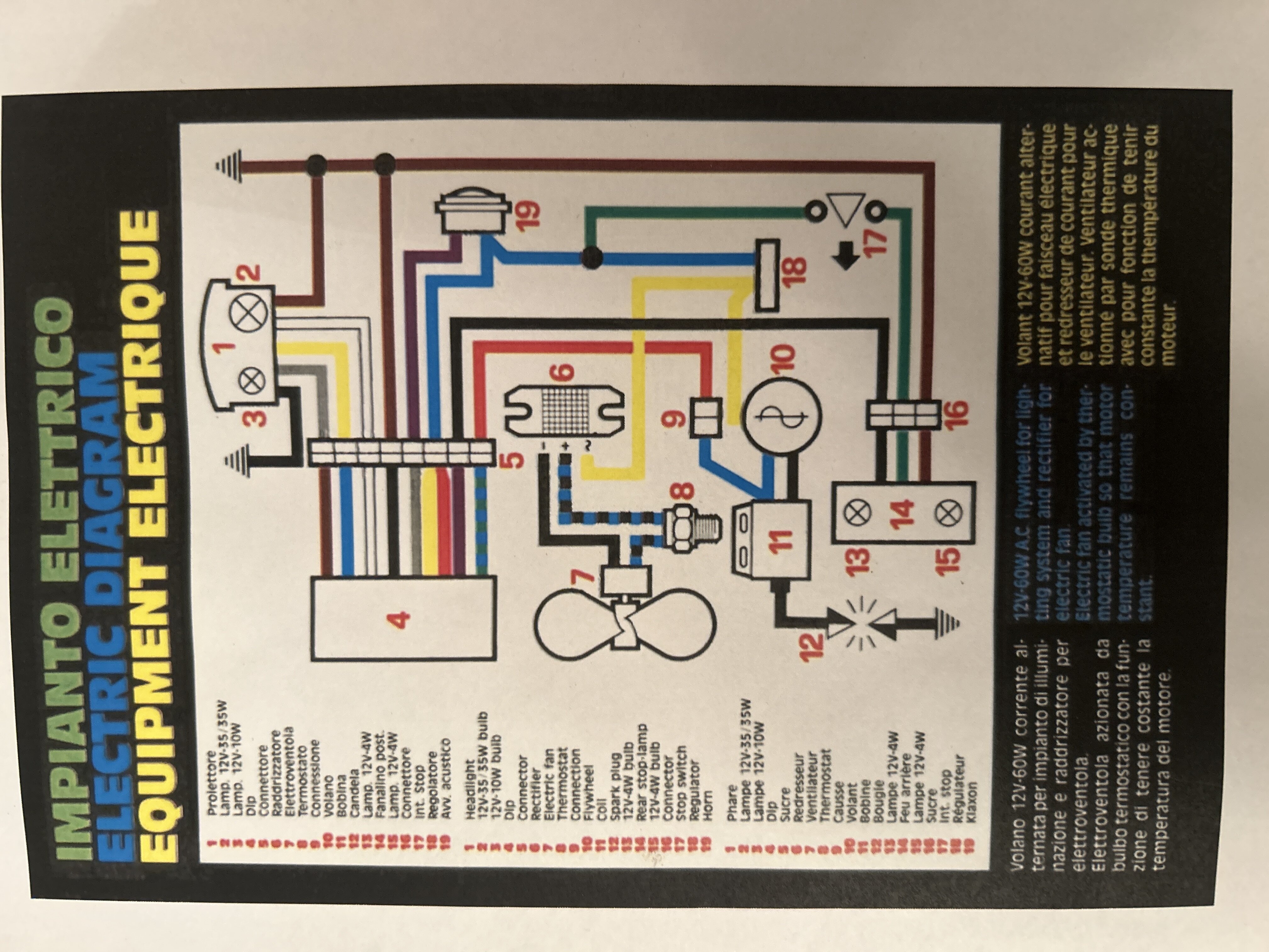
Number 4 on the wiring diagram is the handlebar switches, of which only 1 wire input ( the one attached to the coil ) is relevant as the kill switch. This system has no ignition module like a traditional cdi set up which is why it’s so different and awkward to fathom. I think I’ll send it to motoplat for testing.
-
1990 Zero.pdf parts diagrams for reference
-
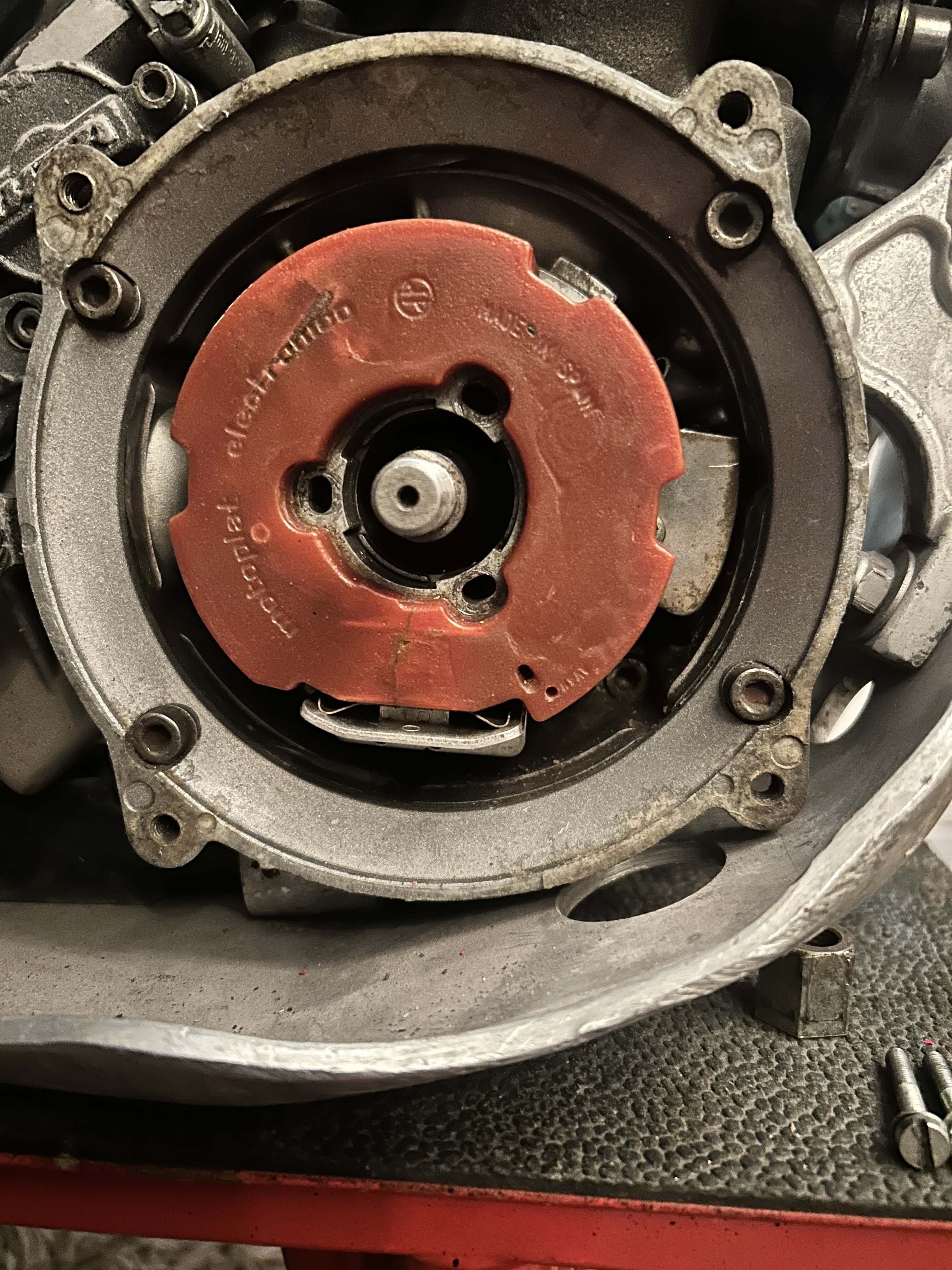
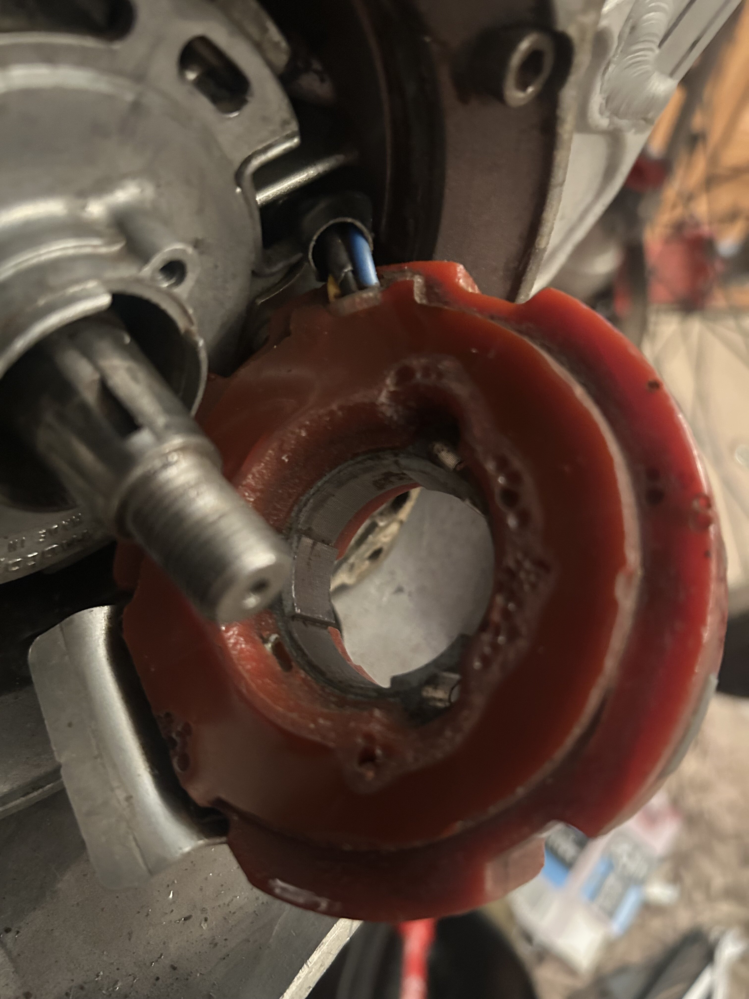
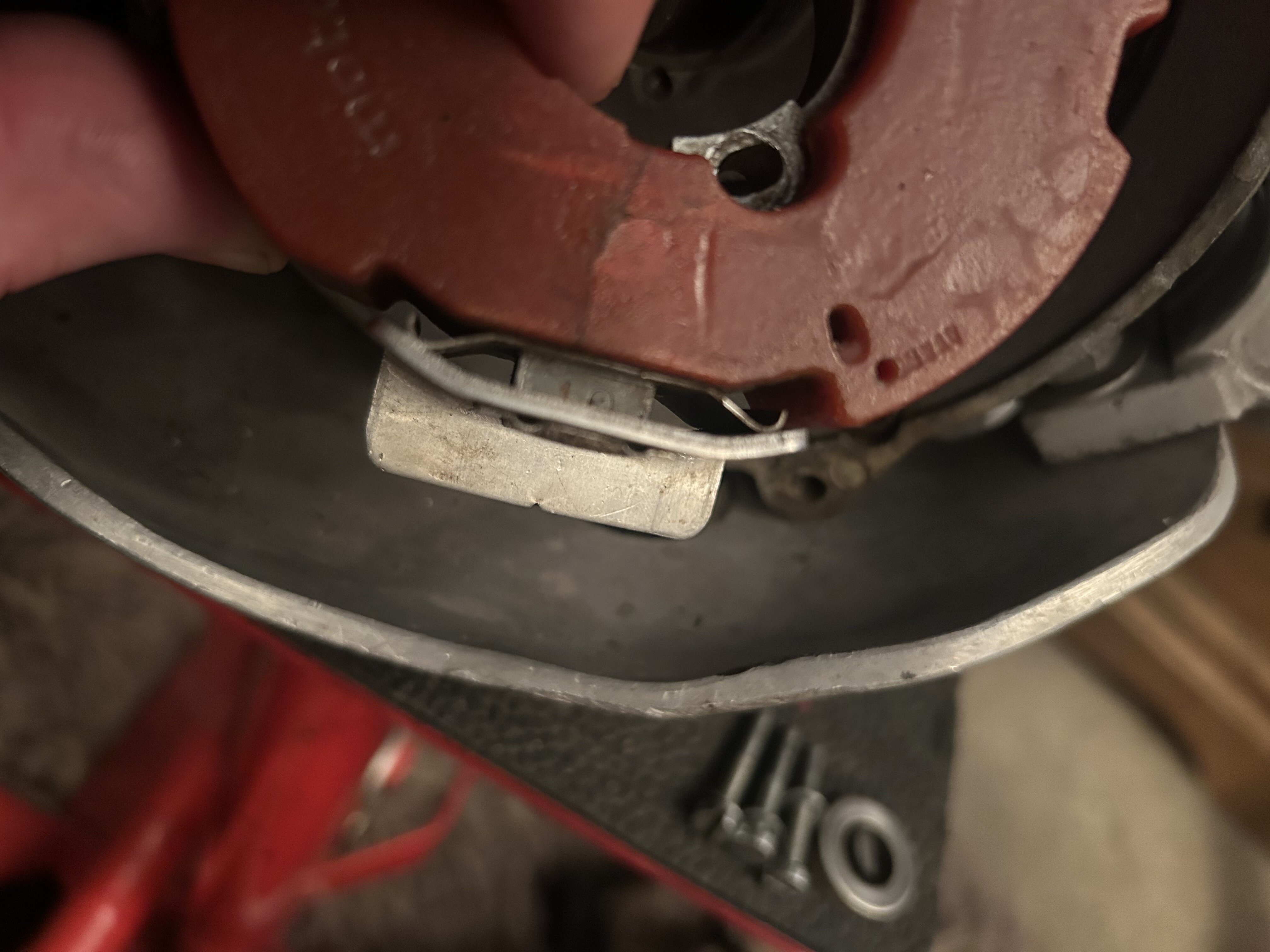
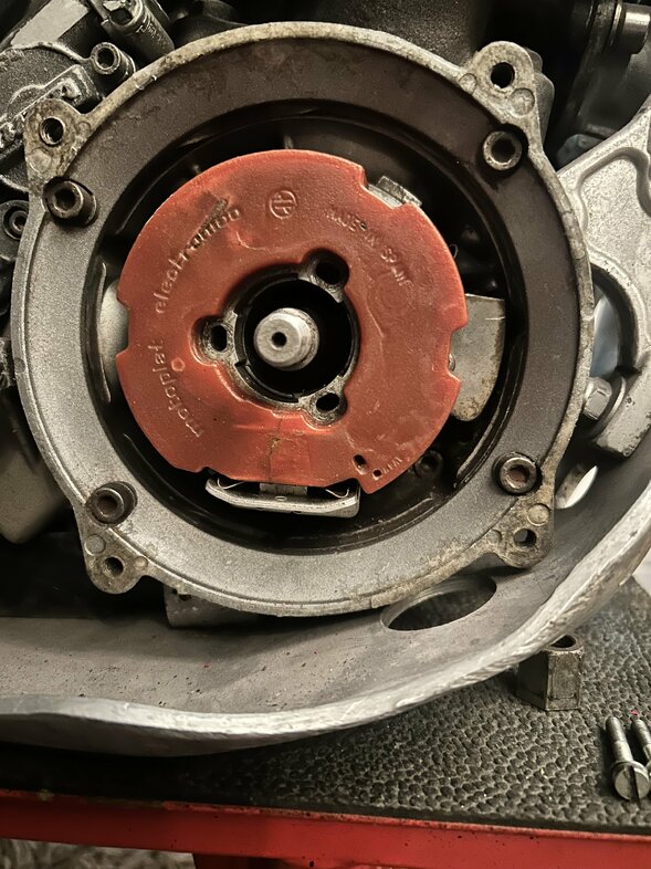
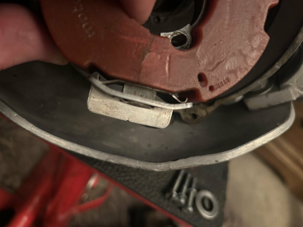
Managed to get the flywheel off despite not having the correct puller. These are what’s inside. The bottom of the windings had a spring loaded plate which may act as a magnetic points system?


-
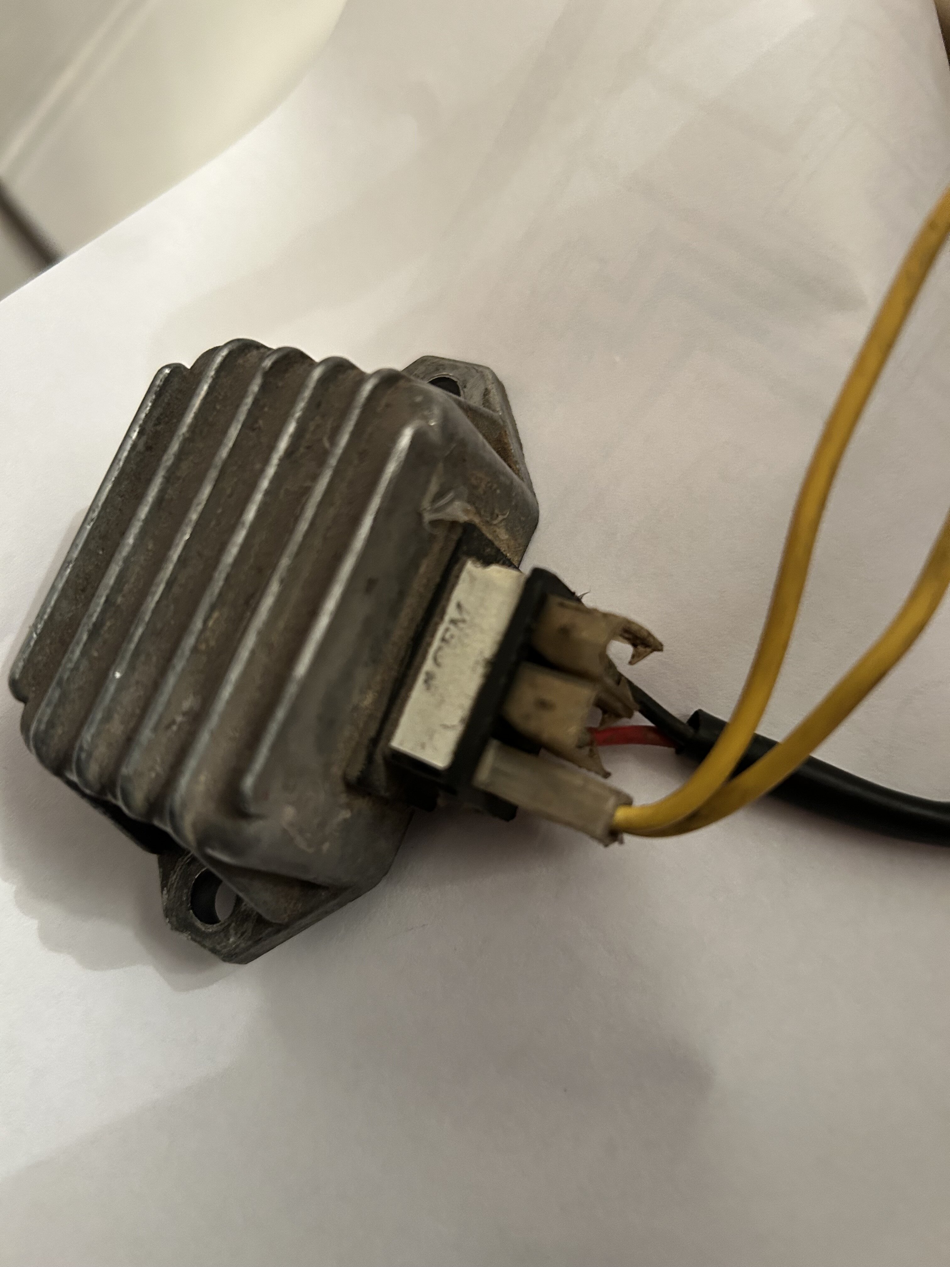
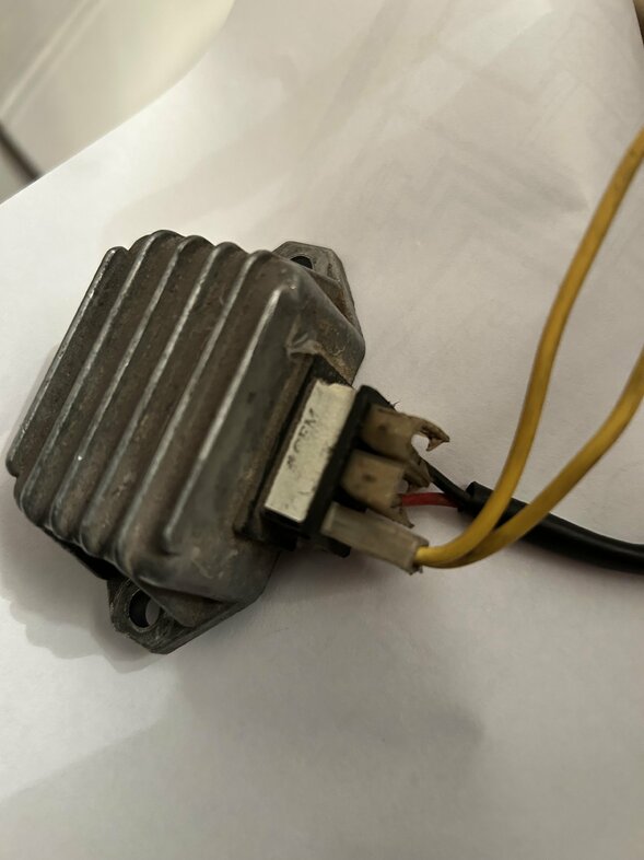
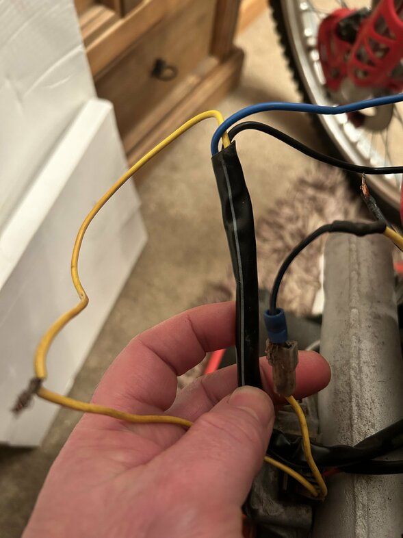
These wires to my “regulator? “ look correct but I have no rectifier which perhaps should be where the wires are twisted.
-
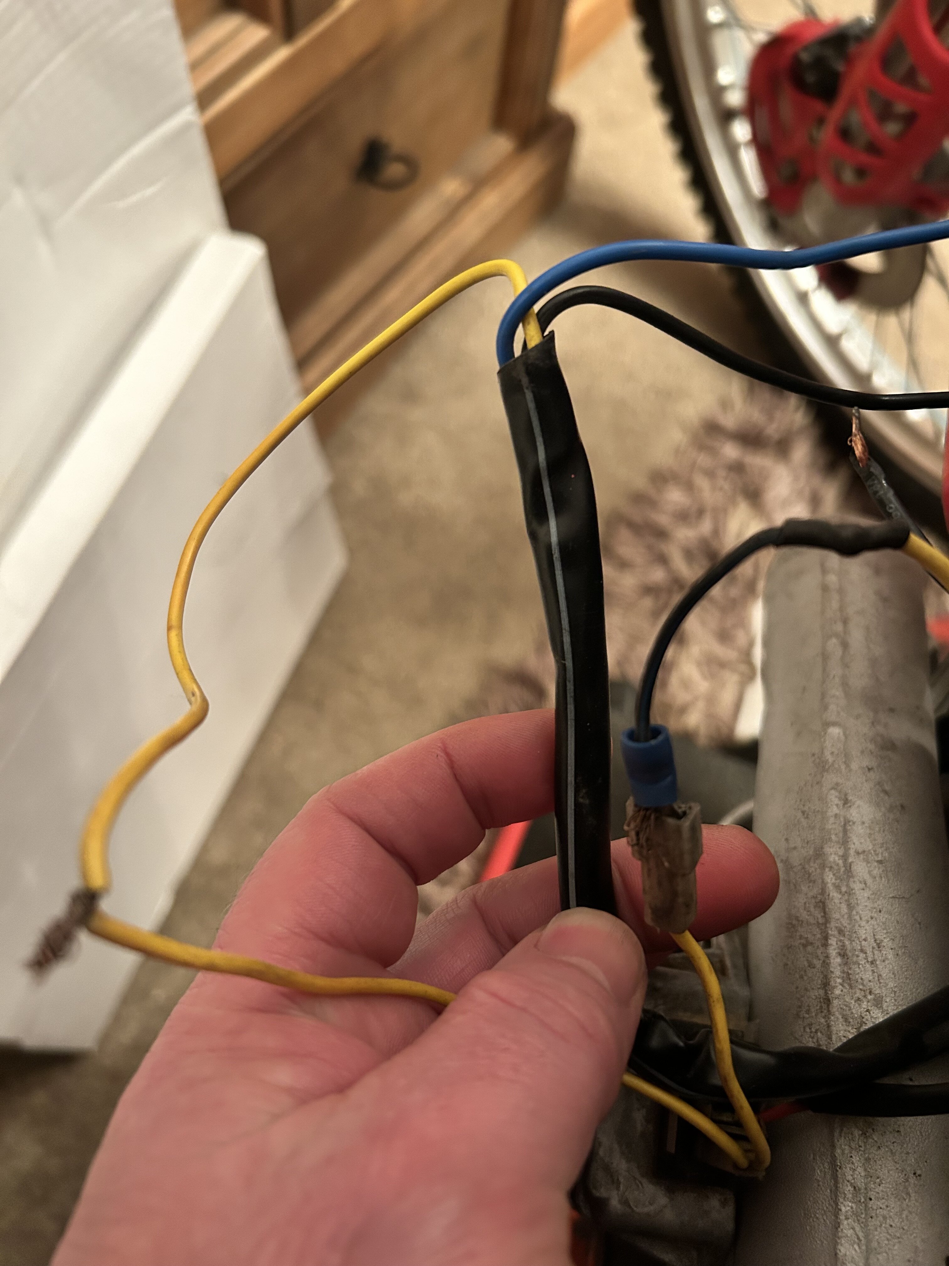
Unfortunately my wiring has already been messed with but wired from stator are correct and are linked as per the diagram. Blue to the coil is a larger connector so must be correct. With a spur going to my kill switch as per numbers 9-5.
-
There is also this old thread on here titled 93 beta zero ignition systems. Let us all know how you get on with it.
-
I have one with no spark too. I have found this so far but can’t find any readings for resistance etc.