As for the shifter not moving. One thought is the shift return spring has slipped up and forced the shifter assembly up. Then when you tighten the tranny in place, it has an extra 2-3mm on the shift drum.
Any chance you can take a picture of the shift shaft assembly on the tranny and post it?
I have posted what mine looks like with a point to the spring. "A" show the shift drum nicely sitting close to the tranny plate. "B" points to the shift return spring which can pop off the shift shaft assembly and force the drum up 2-3mm.
Hmmm, from the parts manual that easy start system looks a lot like the capacitor. Have a picture? I lopped off the mounting brackets on the capacitor before tucking it under the headlight.
Regaurdless, if you dont have the battery under the headlight, then you should have a bunch of room to mount the easy start black box.
White is essentially ground (its less than 0.8 ohms)
Pink and Yellow are 1.3 ohms - both have infinite resistance to all other wires including ground. It appears to match my original schematic as a ground isolated high current field coil.
Black to Ground (white) are 180 ohms - both have infinite resistance to pink or yellow. It appears to match my original schematic as a low current grounded field coil.
So one question has been answered: white is ground.
One question left: should I short the pink and yellow or leave them open. Even though I will not use headlights I would like to keep the coil intact, and also like not to have any back EMF proving resistance to the engine (I dont think - but not sure - the latter matters, its just my lack of knowledge in this area)
Maxbikes: I am still interested on why you are concerned that the XL185 schematic will destroy the CDI.
if you use that diagram you will burn out the cdi unit.dont know why I bother giving out advise.i only give advise if I know the correct answer.i wont bother again.
I am asking of advice and very much appreciate it. I would like to understand why it would burn out the CDI. My only guess is that the AC voltage coming from the alternator is very noisy and full of spikes. My assumption is that the CDI (a 5 wire AC based CDI) has the proper on-board rectification, regulation and filtering to operate properly. However this is a guess from an armchair which is usually about as good as any other "theory".
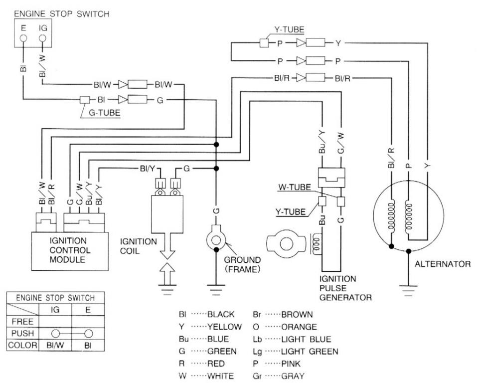
Although the XL185 diagram does not quite match the colors of the TLR200, here is what I gleen from it:
On my TLR200 CDI
* green & blk (w yel) - coil
* blue & green (w wht) - pickup
* blk (w red) - alternator
* blk (w wht) - kill switch
* grn - ground
On the Alternator
* pink
* yellow
* black - to CDI
* white???
The two things I am not sure about are:
(1) alternator pink and white: should these be shorted (as per the original schematic) or should they be left open circuit?
(2) alternator white: what the heck do I do with this?
I am stripping down the wiring harness on my 1986 TLR200 to the bare minimum. I have everything all figured out except one thing. The alternator has 4 wires coming from it:
pink
yellow
black
white
Since I will have no lights I will connect pink-white together (see schematic for XR200 with no lights)
I can get the DID Dirt Star 36 hole rims for a good price. Could these be used for my TLR200 with drum brakes? I am thinking there *might* be some variability in the angle of the spoke holes, but I am not sure how much.
The "clutch axis fixer" (called on the explorer) which is the same as the "primary shaft locker shaft" (as called on the 2013 TR280i) was not on the 2011 models. I was told this part was an improvement so that the clutch engagement point would remain the same as the bike was run through it's paces.
If the "clutch locker nut" starts to loosen, your clutch will slowly not engage. It will feel like there is something in the way (and there is!). IF the "clutch locker nut" falls off (which happened on a bunch of 2012 explorers) the clutch will not engage at all. Don't be a dope like me and force it - bad things will happen.
If you need to tighten this nut do the following:
(1) remove the clutch cover (see the PDF from OSSA canada) and then the nut will be exposed.
(2) The "clutch locker nut" is a LEFT HAND THREAD.
(3) clean off the nut with brake cleaner
(4) clean off the shaft with brake cleaner (this is *not* easy as it will pollute the oil and clutch plates - so be careful and use lots of paper towels)
(5) use BLUE locktight on the nut
(6) hand screw on the nut (LEFT HAND thread)
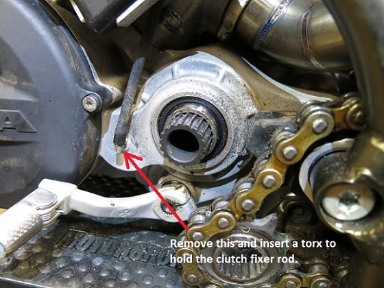
(7) remove the oil breather and insert a torx (T10 maybe?)
(8) tighten the nut gently - I dont think I used more than 4-5 Nm
What sits behind the hose is a bearing for the primary shaft, held in by a circlip. The primary shaft is hollow but there is a long slender rod with a nut (called the clutch fixer rod) through the centre of the shaft. This little clutch fixer rod is hollow.
This just a guess, but I could see oil coming out of the breather for a couple of reasons:
(1) enough oil in the crankcase to go above the primary shaft and into the clutch fixer rod. Was your crankcase possibly way overfilled? I dont have a problem with 450cc of oil.
(2) The clutch fixer nut has come loose and as the bike tilts, oil gets in the primary shaft and then gets sloshed down to the end. If this was a problem your clutch would probably not work or at least acting up.
(3) Laying the bike on the brake side would load a bunch of oil into the primary shaft and into the hollow centre of the fixer shaft It might take a bit for the oil to drain - I say give it a couple of weeks and see if it goes away.
...of course this will all be blown out of the water when PeterB sees your issue.
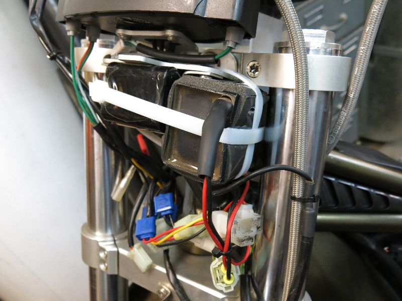
I cut the wings off the capacitor, wrapped weather stripping foam around it, then strapped it to the battery under the instrument cluster. I considered making a bracket, but wanted to test out this location first before doing something more sophisticated.
I wired it in as follows:
* Red lead on capacitor to red lead on head light connector
* Black lead on capacitor to the black wire on a plug that had a black wire and black/wire wire. I wired it to the wiring harness side.
I will permanently leave the capacitor here. It will make swapping the seat on and off easier.
I have read several complaints about the front end being much too light when the steering head angle is modified. I figure I may as well fix it up while doing the rest of the bike.
... and I found one, so I will be picking it up Friday - yippee!
Hey guys, I dont have my TLR200 restoration bike yet, still keeping my eye out (pretty hard to find in Canada). In the mean time, I have been reading and reading the various restoration projects.
I plan to modify the steering head angle. I have read a couple of posts and I will insert 6mm in the top tube for a 2 degree angle change.
But what about the swing arm? How much do I lengthen it out? Where should I make the cut - will it screw up the shock length?

Ossa Gearbox
in OSSA
Posted
oops, here's the pic...