It might work. The FRB (I think on my 2021 epure Race there is a PRB dongle) needs to be able to supply the current for the Hall sensor in the throttle. I tried a hall throttle sensor which was pulling 5mA from a 5V supply and it affected the operation of the motorcycle. The haptic feedback on the MAP select stopped working. I could still cycle through the MAP settings, but the slight vibration normally associated with each press of the MAP button was gone. I did not keep the Hall throttle sensor installed as I am uneasy about lugging down the supply from the controller. If I've read the controller manual correctly it is likely the 5V domain is an isolated supply with a separate ground from the 12V domain (lights, not sure what else).
I have not found a lower current draw Hall throttle. If you are successful please post the model of throttle you use.
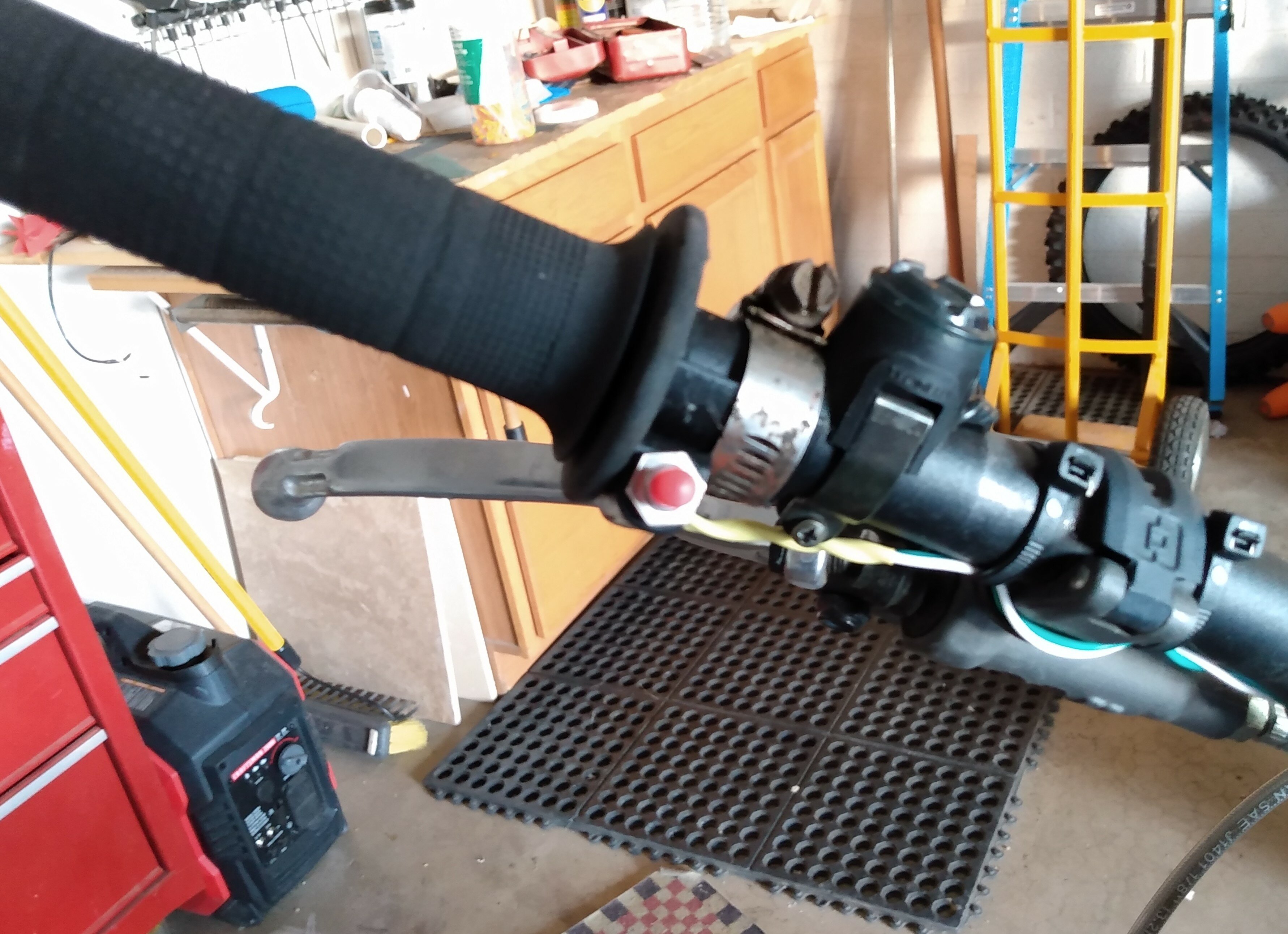
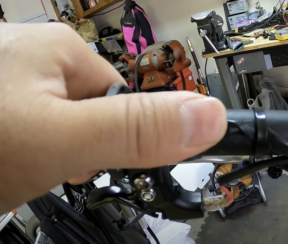
I did install a push button switch giving either full regen or no regen. It is nice. I use it a lot. Maybe too much as the one I built, photo attached is a cheesy switch and may possibly fail when I am counting on it. But, almost never ride in the wet and I like the angle of the switch mount which makes it pretty ergo.
I just did an underwater river crossing this past weekend lol. Now you guys have me scared! I really need to get more educated on electrical stuff but for what it's worth, I ride in the pouring rain and regularly cross 2' depth water on this thing. The only time I ride my 300 2t now is on longer, faster rides away from my house.
I have not performed a "turn-on turn-off" experiment with my EM to prove root cause of the shock I received. I did make measurements of resistance (ohms) at many locations on the motorcycle and think I know what happened.
My measurements:
How I measure:
I use a hand-held multi-meter (DMM) and do not know how many volts the DMM applies when it measures resistance. Other hand-held DMM's I've used would apply about 2V when operating in resistance measurement mode. I will assume the DMM I used also applied about 2V to make the resistance measurement. (For readers who are wondering about this: Ohms law is V=I*R or in words the voltage drop across a resistance is proportional to the magnitude of the resistance multiplied by the amount of current flowing through the resistance. The DMMs I've used apply a voltage and measure the resulting current, then do the math to get the resistance.) Maximum resistance range on my DMM is 2M*ohm.
I used the standard probes that came with the DMM. My probes have a sharp tip, like a small nail. All measurements were made by either lightly pressing the tip of the probe to metal on the bike or, for comparison, grinding the tip of the probe into the metal to break through the anodization.
What was measured:
Motor case to motor case. The motor case is natural looking aluminum and I assumed it has the thinnest layer of anodization. DMM probes lightly placed on the motor case returned essentially 0 ohms probe tip to probe tip. I did this at many locations on the motor case and conclude the motor case is a reasonable ground point. This also taught me how much pressure was required to get a good contact to the motor case from the probe tips.
Handle bar to handle bar where the bars are anodized (black anodization). Lightly pressing the DMM probes tips to the anodization returned an open circuit measurement on all resistance settings of the DMM. I conclude the anodization is a good electrical insulator for small voltages.
Handle bar anodization to motor case: Pressing one probe tip from black anodization region of handle bar with other probe tip on motor case returned open circuit on all DMM resistance settings. I tried many anodized locations on the handle bars and several spots on the motor case. All returned open circuit.
Grinding probe tip into handle bar anodization to motor case: Grinding a probe tip into the anodization on handles bars with one probe tip to the other probe tip on the motor case returned less than 100 ohms.
Clutch lever to motor case: Probe tip to clutch lever (aluminum lever) with other probe tip on motor case returned open circuit. Note: I have teflon plumber's tape wrapped on handlebars so clutch lever has a chance to rotate if I drop the bike.
Kill switch attachment screw to motor case: One probe tip on the head of the screw of the clamp that holds kill switch to handlebars other probe tip on motor case returns less than 100 ohms. I have kill switch on left side, clutch side, of bars.
My guess about what happened:
I received a shock at an event where it was raining off and on. Bike had less than 20 hours on it. The battery level indicator is a voltmeter and full battery voltage is routed to it, so full battery voltage is available at handlebars. I suspect water, sweat, mud, formed a conductive layer on the surface of the handlebars. The bars were in pristine condition with no scratches through the anodization. I suspect the layer of water made a path connecting clutch lever to some electrically hot point inside the battery level indicator. I was discussing the bike technology/features with the trials master when shock occurred and suspect (but don't really remember) that I pantomimed pressing a button for regen braking by pressing thumb into clamp of kill switch. I suspect this because that is exactly the kind of thing I would do while talking with someone, gester with my hands. So: Goo on outer surface of handlebar and clutch makes connection to hot terminal in battery level indicator. Handlebar surface electrically isolated from ground, clutch lever electrically isolated from ground, finger on clutch, thumb presses into ground connected screw completing the circuit.
I have not done an experiment to try and prove the above and know it is a lot of handwaving.
I have dropped the bike a bunch in rocky terrain and the anodization on the handlebars is no longer pristine. There are many points on the bars that measure low resistance to the motor case. If it looks like I'll be riding in the rain I plan on making sure levers are well connected electrically to the motor case. The easiest way to do this in my opinion is to rub off the anodization on the handlebars at all clamp locations. I may try and add some insulation under the battery level indicator, like a piece of inner tube. I have about 100 hours on the bike and have had just the one incident.
I think this is the right power connector for the battery. They've got a cover for it. I'm thinking of printing a cap so when I pull battery out of bike the terminals are protected.
On the surface, sounds good, when you only think of heading down hills. In practice, throttle closure occurs in too many different situations other than downhill.
With a gas engine, rolling off the throttle is followed by continued flywheel engine inertia. So, the Electric Motion, as it stands, is already a bit of a shock to new riders as rolling off the throttle does not have that same inertia, and forward motion ceases much faster. If you add regenerative braking to the throttle action, that would even be more severe.
Think about heading uphill on a gas engine bike. You always roll off a bit and let flywheel inertia carry you over the crest. With a stock Electric Motion, you quickly learn that you better not do that. Even worse if you tied regen braking to throttle closure.
On a downhill run a gas engine provides engine braking, as the rear wheel tries to drive the engine at a faster RPM than it wants to go. In other situations, the gas engine at is still providing a bit of forward momentum while at idle. That characteristic is what the new "tickover" feature on the 2022 EM is trying to imitate. What you are suggesting is the opposite in that closing the throttle would not only stop producing power altogether, but even start resisting forward motion. I don't think that in the end it would be a desired characteristic.
If regen braking were to be linked to any trigger other than its own separate switch, it might work by linking to the front brake lever. It may be a total bust, but would be an interesting experiment. The same type of front brake switch that triggers a brake light could be used to trigger regen. Sounds plausible that if you want the front brake on you might want the rear wheel to experience regen drag as well.
Alternatively, it might well work if the switch was on the rear brake peddle. If it were setup such that the peddle in its full up position closed the switch and turned off regen, the the very moment you pressed the peddle down (even before starting to engage the rear brake) the regen would kick in. Further pressing down would add the physical brake to the regen.
It seems the FRB when asserted disables the throttle. I guess that makes sense, can't simultaneously use the motor as a generator and a motor. I no longer think having FRB assert with either brake is a good idea. Can't use the brakes and spin up the flywheel.
I am also wondering if the FRB is a good idea at all from a failure mode aspect. If the mechanical switch fails open, no big deal, just lose the ability to assert FRB. If the mechanical switch fails closed then lose the motor. Even at my low level of riding I often am on rock where I would dislike losing the motor. I'm curious if anyone knows if the factory EM FRB switch is a single fail component, or a multiple fail component. Single fail meaning only one component has to fail to inadvertently assert FRB, multiple meaning two or more components have to fail to inadvertently assert FRB. My homebrew switch is single fail and is coming off the bike today.
On the surface, sounds good, when you only think of heading down hills. In practice, throttle closure occurs in too many different situations other than downhill.
With a gas engine, rolling off the throttle is followed by continued flywheel engine inertia. So, the Electric Motion, as it stands, is already a bit of a shock to new riders as rolling off the throttle does not have that same inertia, and forward motion ceases much faster. If you add regenerative braking to the throttle action, that would even be more severe.
Think about heading uphill on a gas engine bike. You always roll off a bit and let flywheel inertia carry you over the crest. With a stock Electric Motion, you quickly learn that you better not do that. Even worse if you tied regen braking to throttle closure.
On a downhill run a gas engine provides engine braking, as the rear wheel tries to drive the engine at a faster RPM than it wants to go. In other situations, the gas engine at is still providing a bit of forward momentum while at idle. That characteristic is what the new "tickover" feature on the 2022 EM is trying to imitate. What you are suggesting is the opposite in that closing the throttle would not only stop producing power altogether, but even start resisting forward motion. I don't think that in the end it would be a desired characteristic.
If regen braking were to be linked to any trigger other than its own separate switch, it might work by linking to the front brake lever. It may be a total bust, but would be an interesting experiment. The same type of front brake switch that triggers a brake light could be used to trigger regen. Sounds plausible that if you want the front brake on you might want the rear wheel to experience regen drag as well.
Alternatively, it might well work if the switch was on the rear brake peddle. If it were setup such that the peddle in its full up position closed the switch and turned off regen, the the very moment you pressed the peddle down (even before starting to engage the rear brake) the regen would kick in. Further pressing down would add the physical brake to the regen.
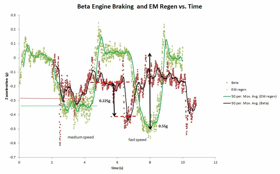
Thank you for the response. I've been considering putting it on the rear brake similar to what you describe. I had not considered the front brake and agree that is an interesting experiment. After reading your first few paragraphs I downloaded a physics app on my phone and made a bunch of deceleration runs using a Beta 250 Evo and the EM with and without regen. Set all tires to 5 psi and used a paved surface. Tried to approximate 3 different and equal speed levels for each bike, two trials at each speed level. At really low speeds there isn't much difference between Beta and EM. At moderate speed the EM with regen has about 25% more deceleration. Higher speeds the EM is about doubling the deceleration of the Beta. No speedometers, used the apparent wind as speed indicator. Beta was in 1st gear the entire time. I am now aware how unaware I am about how a bike is behaving under me. I did not realize the EM had significant difference to a gas bike until the immediate head-to-head comparison.
I am interested in what you figured out with the regen. I've got parts on order to make my own switch assembly. First I am going to do some measurements and experiments. The controller on my 2021 Race has a PRB dongle which matches the video on the EM website that teaches how to install the FRB. If I looked correctly at the paused video the switch they attach has two wires which then connect to the Red and light Blue wires of the dongle. This leaves the black wire of the dongle unconnected. I want to believe the red wire is hot, the blue is for the wiper of a potentiometer, and black is ground. The measurement I will make when parts arrive is to see if red is hot, black is ground. If true, I am going to assume blue is wiper and not connect an instrument to it out of caution (avoid static discharge). The first experiment is to wire a 10K ohm pot to the PRB and see if there is adjustability to the regen braking. What I want to see is if the proportional feature is programmed in, can I find a resistance level which gives regen about the same as applying the rear brake lightly? My ultimate goal is to use a pressure switch on the rear brake, like for a brake light, to operate the regen. The idea being the regen will come on with light brake pressure before the pads really get a grip on the disc. I can then keep my white knuckles tightly wrapped around the grips.
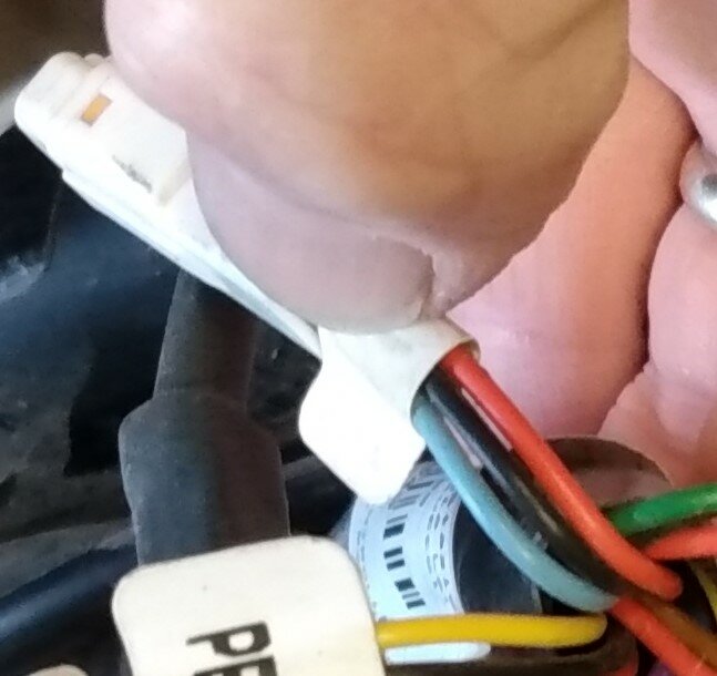
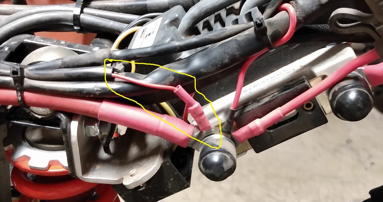
Attached photo of a temporary FRB button under the right side handlebar. Home brew. Attached photo of the dongle on the EM Race 2021. Measured voltage between red wire and black wire on dongle using a Klein tools MM300, DC voltage 20V range ,is 4.8V. Blue wire to black wire measured 0V, black wire to exposed metal of frame of motorcycle measured 0V. According to the video on Central Powersports Distribution web site the FRB switch when closed shorts red wire to blue wire (red and blue reference the attached photo of dongle). Attached pdf is the datasheet for the connector needed if you want to build your own FRB switch.
My experience with FRB: The drag created when activated is noticeable. If my experimentation using it at various speeds and slopes of hill is accurate, and I am prejudiced wanting to believe the following because it seems to be correct from physics, the regen drag is proportional to velocity, and cannot cause the rear wheel to lock. I would like to read other riders experience.
I would also like to hear thoughts on the this: What if regen came on whenever the throttle is shut off? I'm thinking that would mimic the compression drag of an internal combustion bike without risk of causing the rear wheel to slip. Since it comes on when throttle is shut off there is no extra button to use. If regen isn't wanted, squeeze the clutch. If my understanding of the throttle circuit is correct, the throttle signal goes to near zero volts (compared to chassis ground) so a simple inverter (comparator with hysteresis) circuit could send a signal to the PRB blue wire letting it know the throttle is shut off, engaging regen. A more complicated circuit could use a wheel speed sensor to let the rider tailor the magnitude of regen based on wheel spin rate.
Does anyone know how to do the above without an auxiliary circuit board? Point being, if the throttle position voltage signal were split to let it be routed to the blue wire of the PRB dongle and to the siliXcon controller, it might be a software change to make regen come on when throttle is shut off. Since there is no wheel speed sensor this solution will not allow tailoring the amount of regen to bike speed. The hardware to make the split would be a Y cable with appropriate connectors at each end of the Y, assuming the throttle position sensor is using the same 4.8V supply rail. By TPS I mean the potentiometer in the throttle tube assembly on the handlebar.
Spent a lot of time in the wet on my epure and haven't experienced any shocking experiences, I was also curious as to why em put a light on the lanyard kill switch when any magnet will work. I am no electrician and any piece of electric string that isn't 12VDC scares the **** out of me, Q: will the fuse fitted on the bike blow if the short is that serious? Could the shock of been through static there's a lot of nylon in riding gear?
I haven't taken kill switch apart so am speculating; light looks to be red LED. They only need about 2V to emit light. Usually a resistor is in series to limit current so maybe 5V is supplied to the lanyard? The big fuse in the ceramic holder at the rear of the bike is listed at 300A in the parts schematic at Central Powersports Distribution. Given a 50V battery, for the 300A fuse to blow the short is going to need to be about 0.2 ohms or less (V=I*R, R=V/I=50V/300A=0.2 ohms) .
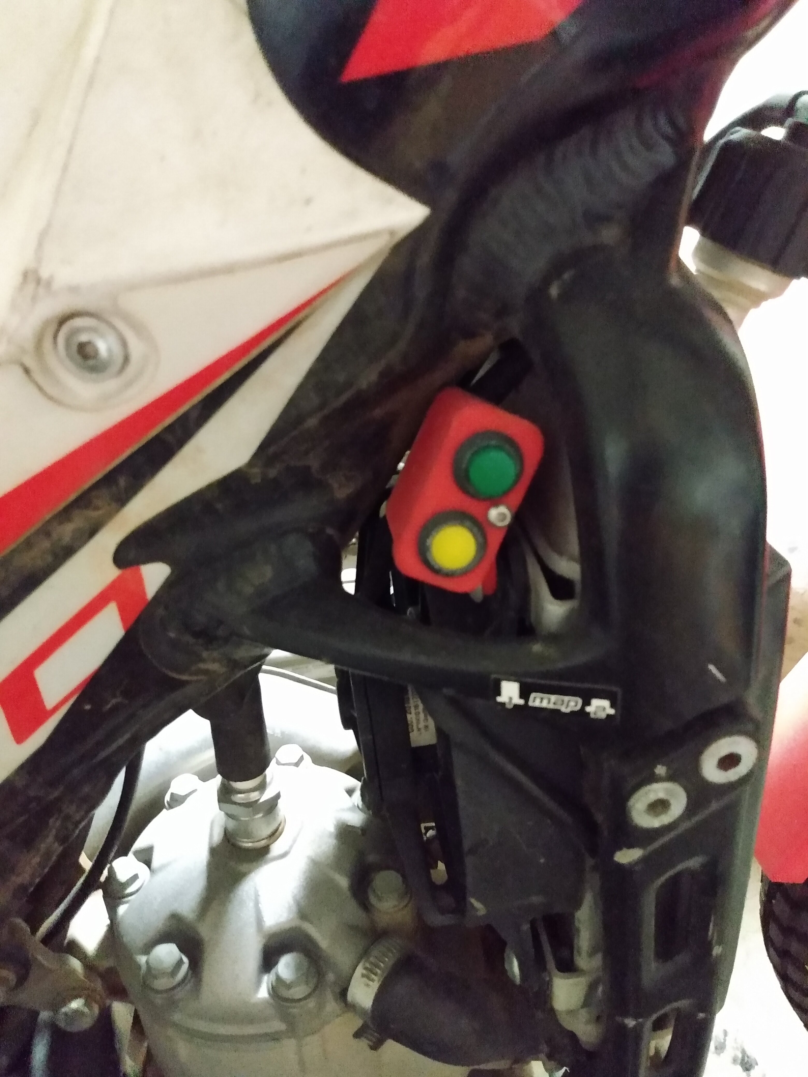
Really cool that you came up with the connectors. Thanks! I have attached a pic I grabbed from one of John's (Ka Uila Motors) YouTube videos. Look below his thumb and you will see a mini-lever style trigger-switch that he is using for his region braking. He is selling the whole setup, plug-n-play ready as an alternative to a push button. To me, that is the solution that makes the most sense. Being skilled in electronics, I want to save the cost by assembling my own. However, so far, all of my search efforts to find a trigger-switch like that have turned up nothing. Danged if I can find one!
I am interested in what you figured out with the regen. I've got parts on order to make my own switch assembly. First I am going to do some measurements and experiments. The controller on my 2021 Race has a PRB dongle which matches the video on the EM website that teaches how to install the FRB. If I looked correctly at the paused video the switch they attach has two wires which then connect to the Red and light Blue wires of the dongle. This leaves the black wire of the dongle unconnected. I want to believe the red wire is hot, the blue is for the wiper of a potentiometer, and black is ground. The measurement I will make when parts arrive is to see if red is hot, black is ground. If true, I am going to assume blue is wiper and not connect an instrument to it out of caution (avoid static discharge). The first experiment is to wire a 10K ohm pot to the PRB and see if there is adjustability to the regen braking. What I want to see is if the proportional feature is programmed in, can I find a resistance level which gives regen about the same as applying the rear brake lightly? My ultimate goal is to use a pressure switch on the rear brake, like for a brake light, to operate the regen. The idea being the regen will come on with light brake pressure before the pads really get a grip on the disc. I can then keep my white knuckles tightly wrapped around the grips.
My 2021 EM Race oil was pretty clean at first 40 hour oil change. As lotus54 said, a bit of fluff on the magnet. I'm thinking of 3D printing a threaded tube for the next oil change so I won't need a paper towel to wipe up the skid plate.
If I got the right parts, JST Type Automotive Connectors 02T-JWPF-VSLE-S and 02R-JWPF-VSLE-S 2 Pin Waterproof Connectors Male and Female Butt Plugs, from Amazon are the right size to plug into the connectors under the top panel. These are assemble yourself connectors so I can't recommend for people who haven't done a lot of electronics assembly. My plan is to find a pushbutton switch in my spare parts pile and wire up the regen braking.
Someone mentioned their EM making a big noise on hard landings...I have a Beta Evo that does the same and figured I was hitting the limit on suspension travel...especially given the sensation in my ankles!
I've used a 2500 watt Craftsman generator to recharge in the field, the 15A charger, no issue, except my riding buddies complained about the generator noise.
I am seeing about 0.8% of full charge/minute of charging time, which works out to just about 2 hours to go from 0% to 100% again the 15A charger.
The following link is a study from the University of Michigan on extending the lifetime of the battery. Lifetime meaning how many charge/discharge cycles you can get.
The attachment is a paper from the U.S.A. Federal Aviation Admin on how to extinguish lithium ion battery fires. I've not heard of these bikes having an issue...I did purchase a 2.5 gallon water fire extinguisher because of the claims in the paper.
If anyone has a suggestion I am interested: Front brake goes soft in a severe tip right hand turn. I've topped off the reservoir and am going to bleed it today. When bike is upright, there is no meniscus visible in the brake reservoir window and brake lever has normal resistance to squeezing. When I practice slow right hand turns with my body way outside so I can really lean the bike and practice stopping and balancing mid-turn, I can see the meniscus appear and it looks like "air" is intersecting the brake line which would explain the softness of the lever. When I topped off the reservoir it spewed oil as the cap and rubber thingy were replaced so I'm not sure how to get any more oil in?
Regarding connectors...the attached data sheet from siliXcon has a "pinouts" section which lists the various connectors. There are several different types used, two pin, three pin, four pin.
Wow , I think I will be sticking with 2 stroke power ,
all this talk of - 50+volts , 800A fuses, mixed with heavy rain , is not convincing me that electric is the future.
Good luck, I hope its a simple fix
My mistake. It is an 800A fuse holder, the ceramic part, with a 300A fuse. Still enough to do welding. Approximate total peak power is 50V X 300A =15kW or about 20 HP. Pretty impressive...
Current path being to the ground via your thumb and feet which i imagine were on the ground when you were stopped. Soaked clothing and boots i imagine would greatly reduce this paths resistance. Where does the lcd negative line go or is it earthed to the bars?
It looks like the LCD has a separate return wire. I'm not going to dismantle anything since it has a warranty and I'm satisfied with everything I've seen that the bike is perfectly safe to operate. I am curious about the model of current flow you propose. Are you suggesting current left the positive terminal of the battery, went through me to earth (ground but I literally mean the Earth since I think that is what you are suggesting) and then found a return path from the earth to the negative terminal of the battery? Or are you suggesting the motorcycle acquired a net charge such as someone shuffling their feet on a carpet, hence a potential difference with respect to the earth, which then was able to discharge through me when my resistance to the earth provided a path? Or something I am not imagining? I'm tempted to set up experiments to test your hypothesis, but I don't understand what you are suggesting. I believe if I understood I could instrument the bike and not have to participate in the conduction path.
I am a bit taken back by them taking those power taps ahead of the fuse. Running 50v from there, all the way back to the LCD, before stepping down just doesn't sound wise, if that is the case.
I suspect that it is deliberate to leave the electronics live on whatever is left of battery power after the 800A event...it let's them have a diagnostic and maybe a warning message like: "RUN!" or "Please enter next of kin"
I agree with the suggestion of checking continuity with a meter. For anyone not knowledgeable about ohm meters, please be aware they apply a small amount of energy to make a resistance measurement. If an integrated circuit is not properly designed the ohm meter can destroy it. My hand held DMM applies about 2V when making a resistance measurement.
Thanks for the suggestion, my riding partners do experience what you describe on occasion at one of our staging areas which sits under some high tension lines. My experience was far from any lines and I immediately expressed to the riders around me did anyone else experience a discharge or see anything...no one else.
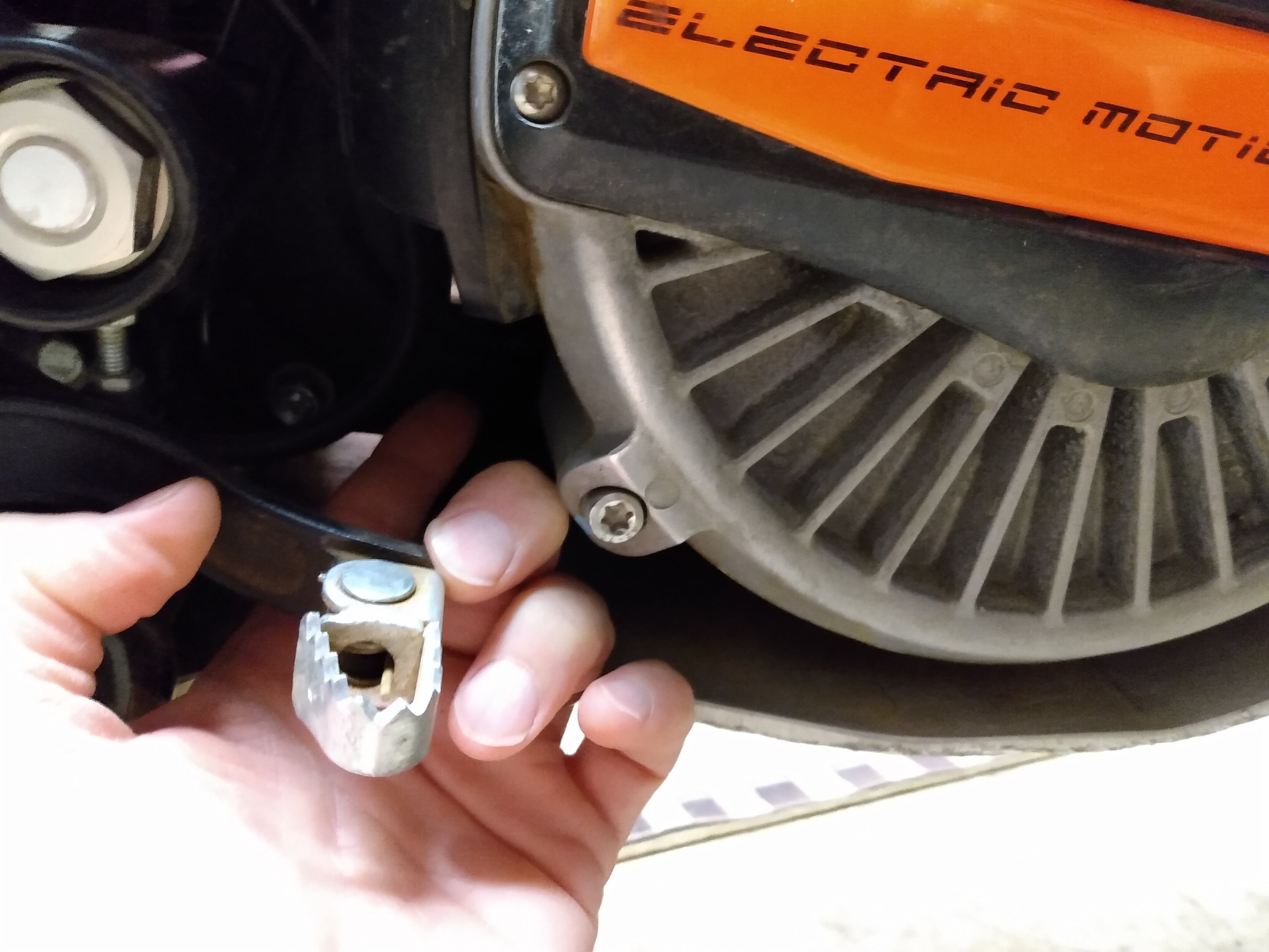
I think I may have traced the culprit, at minimum I am not concerned about operating the bike in dry weather. Attached photo shows the attachment point of the battery +50V terminal. The terminal is one side of an 800A fuse, and the additional wires coming off the terminal are clearly going to melt long before the fuse if there is a short on their side. Point being, I don't think I need to worry about a short induced battery fire. As an aside, one could definitely do some welding in the field with the EM battery...that's got to come at a huge premium price!
In the picture I've circled a red wire that is on the +50V battery terminal in yellow. If I traced it correctly this wire runs to the LCD display (and I want to believe I traced it correctly because it isn't uncommon for an LCD to need more than +5V logic supply. I'm guessing EM chose to use a step-down converter in the LCD rather than a step-up, keeps wire size down). I'm highly suspicious the jolt I received came from the LCD supply line. I'll be even more convinced if someone can give me a reasonable explanation of the current path...
I think for a long term solution, if it is the LCD line, I want my dealer to find out from EM if the hypothesis is plausible, and if yes, what is the current draw of the +50V line so what value resistor could be placed in line to limit any future shock. Or an inductor...but that could backfire severely if a resonance occurs...both inductor and resistor...
Did an event in Arizona where it rained. Seriously, it rained in Arizona. Dripping wet waiting in queue on second loop about midway through the loop, got a severe jolt in the left hand while soaking glove hand had finger on clutch lever and thumb wrapped around grip. Shock was felt throughout my hand and seemed to exit (enter?) at my thumb. I've done enough work with AC and DC (I'm a sparky), including some medical experiments with DC, that I think this was a real shock event. Meaning I don't think it was some nerve pinch or arthritis related garbage. I've not run an experiment on myself to calibrate sensation vs voltage (I've got some mates who would be happy to help), however the magnitude of effect has me thinking it was the full 50V or so of the battery pack.
My dealer has been very responsive and said he has had big bike customers report similar shocks of the left hand which were traced down to an inadequately tightened ground wire. My dealer is going to contact EM for more information.
My dilemma: I want to ride. I know the best way to get a Li-ion battery fire is to short the battery. While a loose ground isn't a short, it is a close cousin. The battery is out of the bike while I contemplate my next move.
I am interested in suggestions on how to proceed. I'll wiggle everything to see if there is a loose connection. I hesitate to dismantle motor less I void warranty?
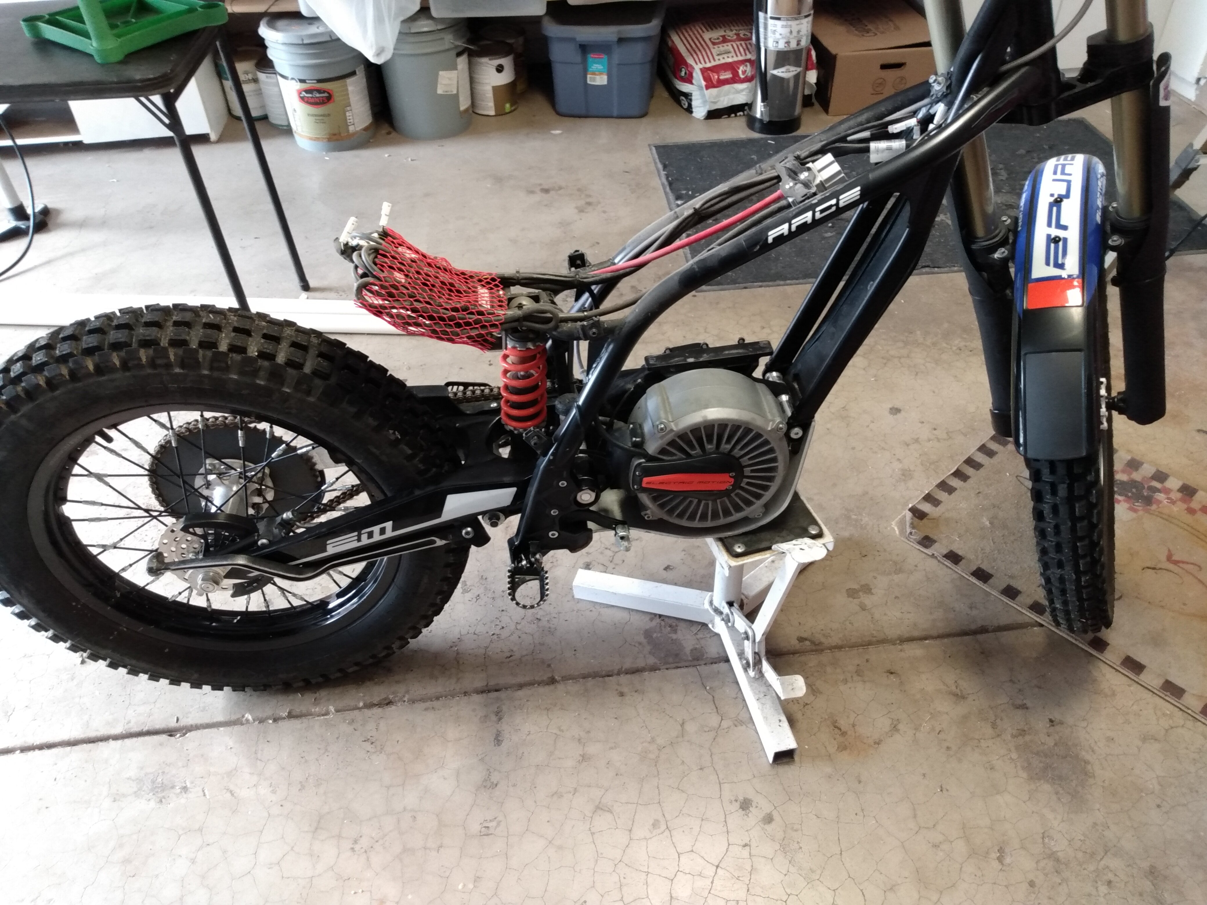
Stripped bike photo attached. The more I do with this bike the less interest I have in petrol powered bikes. This electric stuff certainly has a learning curve, but it seems so much more simple. Is it a siren's song?
Assuming no one has completely rewired your bike and the info in the manual is accurate:
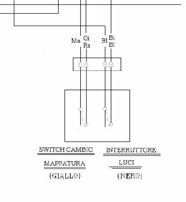
Page 9 shows the wiring diagram, it looks to be in Italian. There's a table giving reasonable translation of the color wires for the 12V, 20W Proiettore Ant. Without using google translate from the 12V,20W that is your headlight.
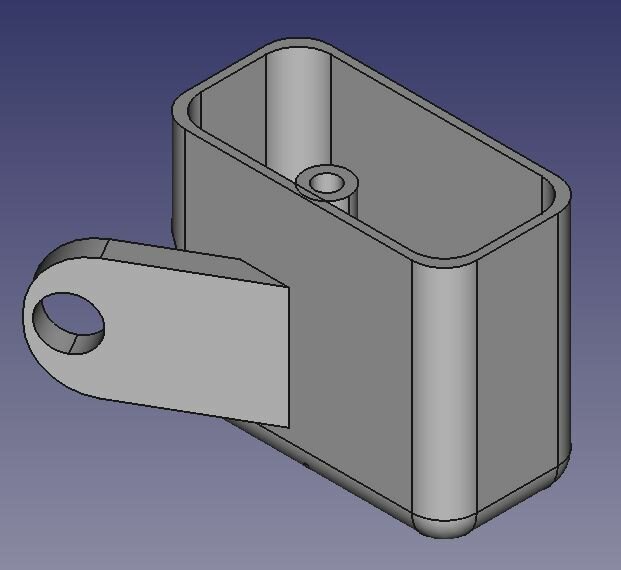
If you want the switch box I 3D printed, shown in the attached photo the orangish rectangular prism with green and yellow switches, we need to figure out how to get the .stl or .std files to you. I don't know how to fool the attach file to take them, it says the extension isn't on the approved list. I'd tell you what part number of switch I am using, except they were kind of junky and 20% of the ones I purchased quit working almost immediately. They are rated 1A at 120V so I figured they could handle 12V, 1.75 A of DC. So far so good. The CAD snip shows the little arm on the box for bolting it to the fan housing. I have many tens of hours of use on it. Not shown is the opening in the bottom of the box for letting water out. I guess it lets water in too...
Second snip is I'm pretty sure the switch wiring detail from the owner's manual.
My 2021 EM Race oil was pretty clean at first 40 hour oil change. As lotus54 said, a bit of fluff on the magnet. I'm thinking of 3D printing a threaded tube for the next oil change so I won't need a paper towel to wipe up the skid plate.
If I got the right parts, JST Type Automotive Connectors 02T-JWPF-VSLE-S and 02R-JWPF-VSLE-S 2 Pin Waterproof Connectors Male and Female Butt Plugs, from Amazon are the right size to plug into the connectors under the top panel. These are assemble yourself connectors so I can't recommend for people who haven't done a lot of electronics assembly. My plan is to find a pushbutton switch in my spare parts pile and wire up the regen braking.
Someone mentioned their EM making a big noise on hard landings...I have a Beta Evo that does the same and figured I was hitting the limit on suspension travel...especially given the sensation in my ankles!
I've used a 2500 watt Craftsman generator to recharge in the field, the 15A charger, no issue, except my riding buddies complained about the generator noise.
I am seeing about 0.8% of full charge/minute of charging time, which works out to just about 2 hours to go from 0% to 100% again the 15A charger.
The following link is a study from the University of Michigan on extending the lifetime of the battery. Lifetime meaning how many charge/discharge cycles you can get.
The attachment is a paper from the U.S.A. Federal Aviation Admin on how to extinguish lithium ion battery fires. I've not heard of these bikes having an issue...I did purchase a 2.5 gallon water fire extinguisher because of the claims in the paper.
If anyone has a suggestion I am interested: Front brake goes soft in a severe tip right hand turn. I've topped off the reservoir and am going to bleed it today. When bike is upright, there is no meniscus visible in the brake reservoir window and brake lever has normal resistance to squeezing. When I practice slow right hand turns with my body way outside so I can really lean the bike and practice stopping and balancing mid-turn, I can see the meniscus appear and it looks like "air" is intersecting the brake line which would explain the softness of the lever. When I topped off the reservoir it spewed oil as the cap and rubber thingy were replaced so I'm not sure how to get any more oil in?


New Epure Owner
in EM (Electric Motion)
Posted
Hello Nacho73,
It might work. The FRB (I think on my 2021 epure Race there is a PRB dongle) needs to be able to supply the current for the Hall sensor in the throttle. I tried a hall throttle sensor which was pulling 5mA from a 5V supply and it affected the operation of the motorcycle. The haptic feedback on the MAP select stopped working. I could still cycle through the MAP settings, but the slight vibration normally associated with each press of the MAP button was gone. I did not keep the Hall throttle sensor installed as I am uneasy about lugging down the supply from the controller. If I've read the controller manual correctly it is likely the 5V domain is an isolated supply with a separate ground from the 12V domain (lights, not sure what else).
I have not found a lower current draw Hall throttle. If you are successful please post the model of throttle you use.
I did install a push button switch giving either full regen or no regen. It is nice. I use it a lot. Maybe too much as the one I built, photo attached is a cheesy switch and may possibly fail when I am counting on it. But, almost never ride in the wet and I like the angle of the switch mount which makes it pretty ergo.