These bearings are so specialised (replacing ball thrust bearings, equally specialised) that even with a number, if indeed you could ever find one, there is no chance that you will find them at your local bearing shop.
(This is of course a chance for someone to reveal which local bearing shop has them in stock - and prove me wrong ...........!!)
Both of the 19mm bolts securing the rear (cast) engine mount bracket were tight (didn't check torque), but there was some play allowing the engine to move slightly i.e. being cast the bracket wasn't a tight fit to the engine mounting lugs.
You can junk the cast bracket and replace with a fabricated steel one, as Bultaco themselves did on later bikes. Bracket should be obtainable new from Inmotion, or possibly secondhand on fleabay, etc. Also check carefully the (cyl.)head steady and fixings.
Don't want to be too hard on you.........I'm sure we all made stupid mistakes as raw novices - I know I did......
However, "culprit of the nasty noise in the engine" is unlikely to be just a nut that's come undone - that's more likely to be merely a symptom of other damage. As vintagenut has suggested, the woodruff key is probably also sheared, with attendant damage to the tapers of flywheel and shaft. Also, depending on the revs. reached (and for how long) when the bike started w.f.o. you may have damaged the conrod bearings. As misscrabstick and pschrauber have said, engine now needs a total strip and rebuild.
On 7/11/2020 at 7:03 PM, 6ril said:
Now I know I can't do almost any of it myself, I'll have to seek (paid) help from a proper mechanic.
Best thing you can do is follow your own admission, and entrust the work to someone who actually knows what he's doing. Be prepared for a sizeable bill...sorry !
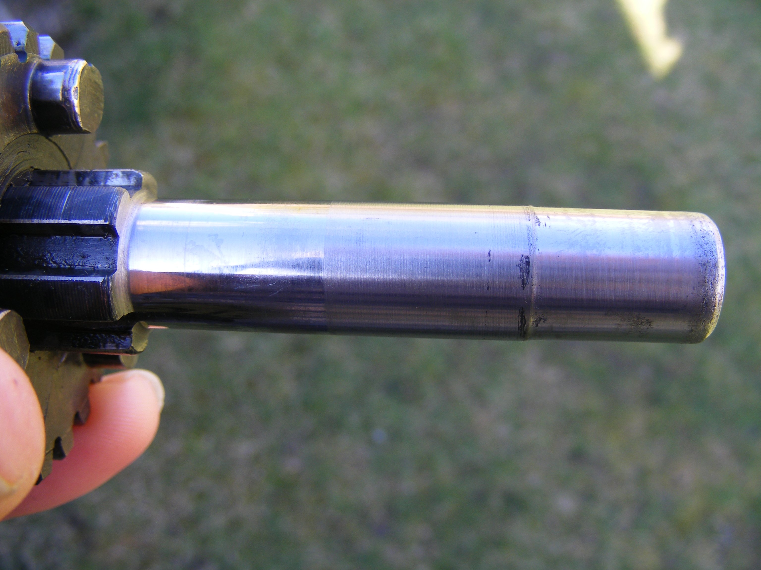
Whatever you decide with your engine, I urge you not to make any non-reversible changes - reducing the interference fit of main bearings "to make assembly" easier would be one such change............you could regret this when your main bearing inner races start to spin on the crankshaft........
Never assume that Bultaco didn't know what they were doing .....
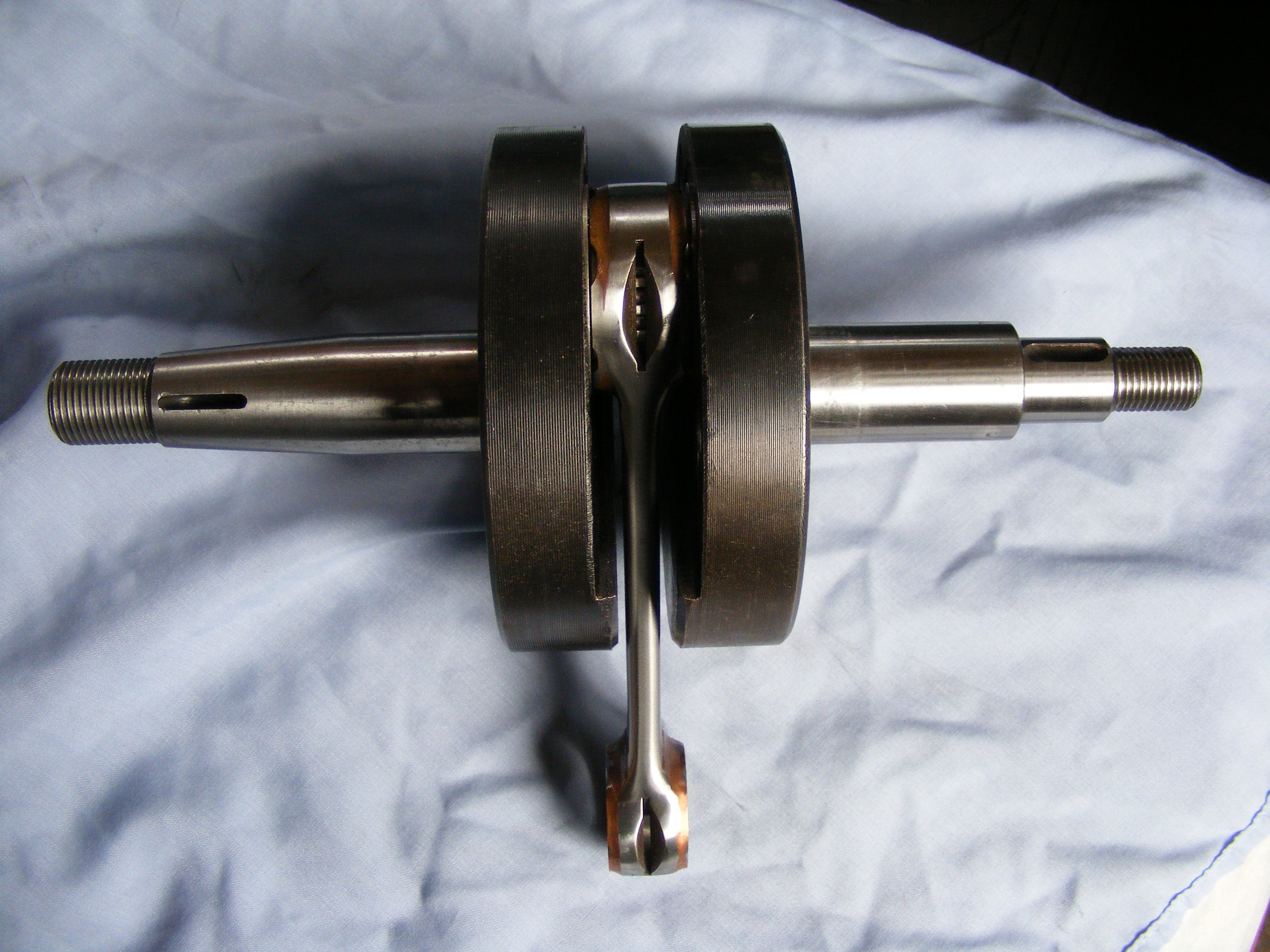
Your con rod assembly looks like :-
As far as I can tell replacements ARE available - this is one bought in January and now fitted to one of my cranks:_
(I was quite surprised to find this crank in a mod. 124 engine, which I believe would have had an 18mm. crankpin originally..! )
Also have o/size Mahle 71mm. pistons, although many have said these are "unobtainium".
"Seek and ye shall find" ?
The availability (or otherwise) of parts is influenced by how soon they are needed, and the depth of your pockets. I have several engines undergoing "the treatment " at the moment and I've not found one that's worked out cheaply so far........
The small hole pictured is the gearbox breather, the only breather in standard form. It needs to be kept clear - if it becomes blocked it can lead to oil leaks and/or g/box sprocket seal failure. Attempts to provide alternative breathing through the filler plug have had mixed results, according to previous posts on the subject.
Over the years Bultaco appear to have experimented with either two or three main bearings / crankpin (and crankwhee)l diameters / conrod location by big-end washers and small-end spacers / location by small-end spacers only. Your conrod/big end bearing with narrow thrust washers is the original type of set up for your engine.
Just because there is a circlip in (supposedly) the centre of the main bearing outers this will not stop the crank from moving in either direction when everything gets hot.
But wasn't that was the very reason the circlip was introduced on later engines..?
17 hours ago, DickyM said:
my bike has a round section circlip fitted between the two drive side bearings. This means that when the drive side crank nut is fully tightend the right side of the crank pulls up to a fixed position with the drive side double bearings pulled up tight either side of the circlip. I.E. The position of the crank is fixed, determined by the circlip, with no lateral movement for any adjustment.
Crankcase gasket must stand proud of cylinder base joint face at assembly, to be trimmed after cases are together and all fixings tightened. This should ensure that there are no leaks at cylinder base.
You seem to have taken considerable care to centralise crank within cases ; what happens when driveside nut (for oil seal sleeve and sprocket/weight) is fully tightened ?
or alternatively assemble crank in clutch side case with normal bearing then lower this as an assembly in flywheel case that has the nj205 bearing installed?
..
Yes.............
Crankshaft needs positive location relative to drive side crankcase half to retain primary chain alignment. Using roller bearing on mag. side of crank also makes crank width and axial location of main bearing less critical.
a bit confused how using this bearing makes it easier to assemble cases?
As the inner and outer races of the roller bearing are separate parts, once fitted to crankshaft and crankcase respectively it's then possible to assemble/disassemble the engine without heat.. See above from the o.p.
The roler bearing you have has axial location in one direction ( a shoulder on the inner race) - have I got that right ?
Why not heat the inner race and fit that to the crank (shoulder to the wheel), heat the crankcase and fit the outer race ("open" side to crank). Inner and outer parts of the bearing are then located independently and you can simply slide the bearing parts together when you assemble crankcase halves.
This of course ignores manufacturer's markings........( and I don't know which way they face on SKF bearing, anyway)....... having NJ series bearing also sets up requirement for the crankshaft width between bearing seats to be controlled to avoid negative axial clearance.
Front wheel has had a steel/cast iron? (ferrous, anyway..) liner inserted. This is the usual means of salvaging hubs which have suffered deterioration of the chrome plating.
Hard chrome originally applied direct to alloy casting. If your chrome is as intact as it looks, keep it unti it fails.
Rear spokes stainless butted, or steel galvanised ?
Gentlemen, thanks very much for your response - I'm almost overwhelmed. How did we ever manage, "pre-internet" ?
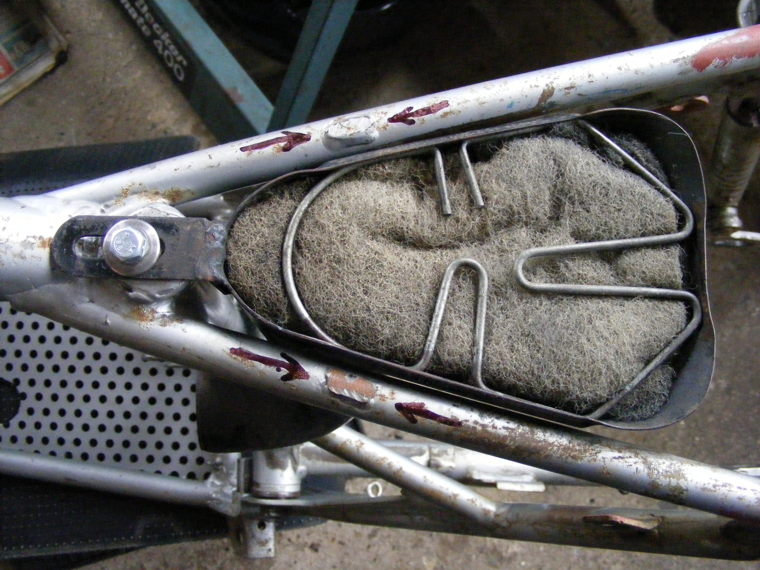
Vintagenut : no tabs on the air filter, and no sign they were ever there. Same thing with my mod. 92 (also '73).
gooey : Alloy tank unit.........do you have a pic. ?
feetupfun : Thanks again for your detailed shots - exactly what I was looking for (and was unable to find elsewhere).
So it seems that the tabs were to support the front of the seat section of the fibreglass tank unit, and assuming the original "long" seat is used, support at the rear is provided by the seat resting on the frame loop ? Perhaps someone can confirm........... Additionally, could they be to maintain a clear "breathing" space above the filter intake ?
This leads me to ask if anyone knows what type of seat was fitted to the UK bikes with Homerlite alloy tank unit.......my bike has a short trials type seat which may not be original, and anyway doesn't extend rearwards as far as the frame loop, meaning any weight placed on the rear of the seat would provoke bending/cracking of the alloy, assuming the tabs were still in place.
Prior to rebuilding this long-term (dismantled) project, I've begun dragging out and examining parts, with a view to doing a trial assembly before parting with serious money on chrome plating, powder coating, etc.
Starting with the frame, I found two sawn/ground off welds on the seat rails either side of the air filter (arrowed in pic.) :-
Anyone out there know what was there originally ? Brackets/ lugs/ a bridge across the filter ? ....and do I need to replace it ? Outer edges of the air filter body appear to stand slightly proud of the frame rails, and there are marks on the underside of the seat part of the tank/seat unit.
Bike is a UK supplied and registered example from new (Aug. '73) and came to me with Homerlite fuel tank, which I assume is original -(this would have replaced the usual fibreglass item fitted for other markets, I believe). I know these are notorious for splitting the welds between tank and seat panel; I'd like to get the fit right.
Re the rear wheel spokes, the originals were (single) butted stainless steel , M4 X 3.5mm and used on models 27, 49, 80, 85, 91 & 92:-
(from the top)
r.h. inner/ outer - 18 off length 189/195mm ? )
l.h. inner - 9 off " 165/167mm ? ) depending on which parts book you are looking at
l.h. outer - 9 off " 162/165mm ? )
The stumbling block for obtaining replacements is that l.h. outer - I couldn't get any for years until I found a seller in the US with NOS. (I don't think spoke suppliers are very keen on replicating the double bend in stainless, a pretty unforgiving material). The double bend is to allow sufficient offset of the rim/tyre to clear the chain line and chainguard. Ultimately, these are the first spokes to suffer damage, or breakage if the chain derails...............
The alternative would be a set in single gauge galvanised, similar (but not identical, unfortunately) to Pursang fitting.
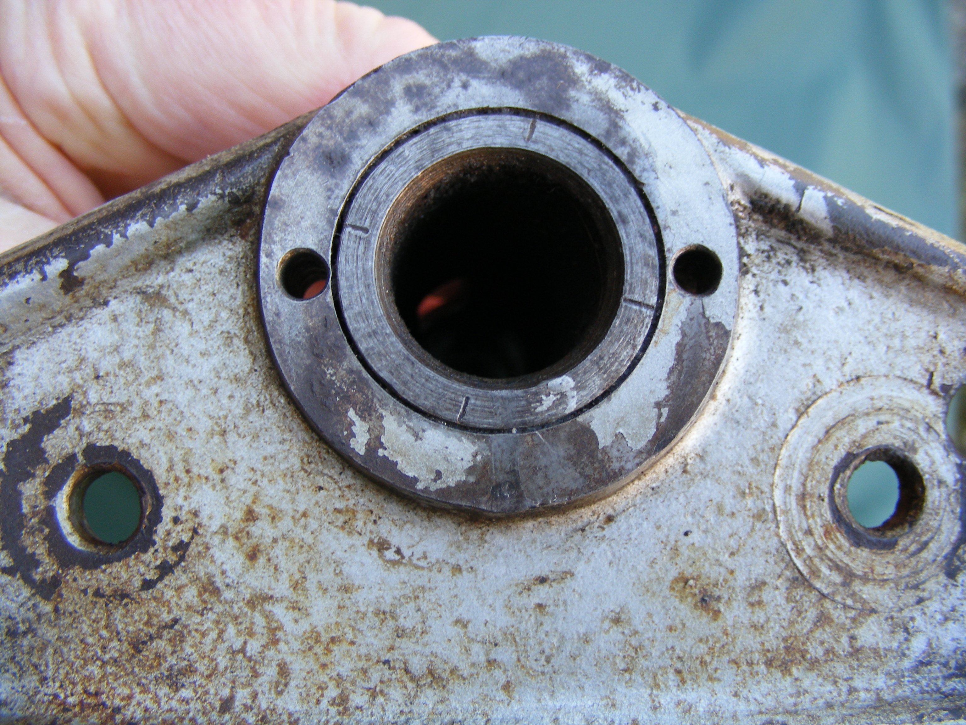
Re removing steering head lower inner race : these can be VERY tight on the stem (unnecessarily so, in my opinion) but if your lower yoke is like the one on my M85, Bultaco very thoughtfully provided two holes for this very purpose :-
I use a Hilti nail - hard as hell and at 3.85mm. dia. exactly the right size - the more affluent/better equipped would use a parallel punch.
Unfortunately, you may find that once you've removed the race from its lower position you have an equal struggle getting it off past the upper race position....
If your yoke doesn't have drillings, it's probably down to grinding away and splitting the race with a chisel.
As you have already found, cylinder head nuts and carb. fixing are 8MB = m8 x 1.00, although the other end of the relevant studs are 8MA = m8 x 1.25 where they thread into the crankcase and carb. stub, respectively. (Also applies to the two cylinder head studs in the barrel)
6MA = m6 x 1.00 pitch
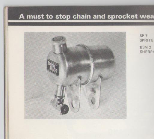
Re the tap in the frame top tube : how does the oil/liquid get in there ?. The mind boggles..........
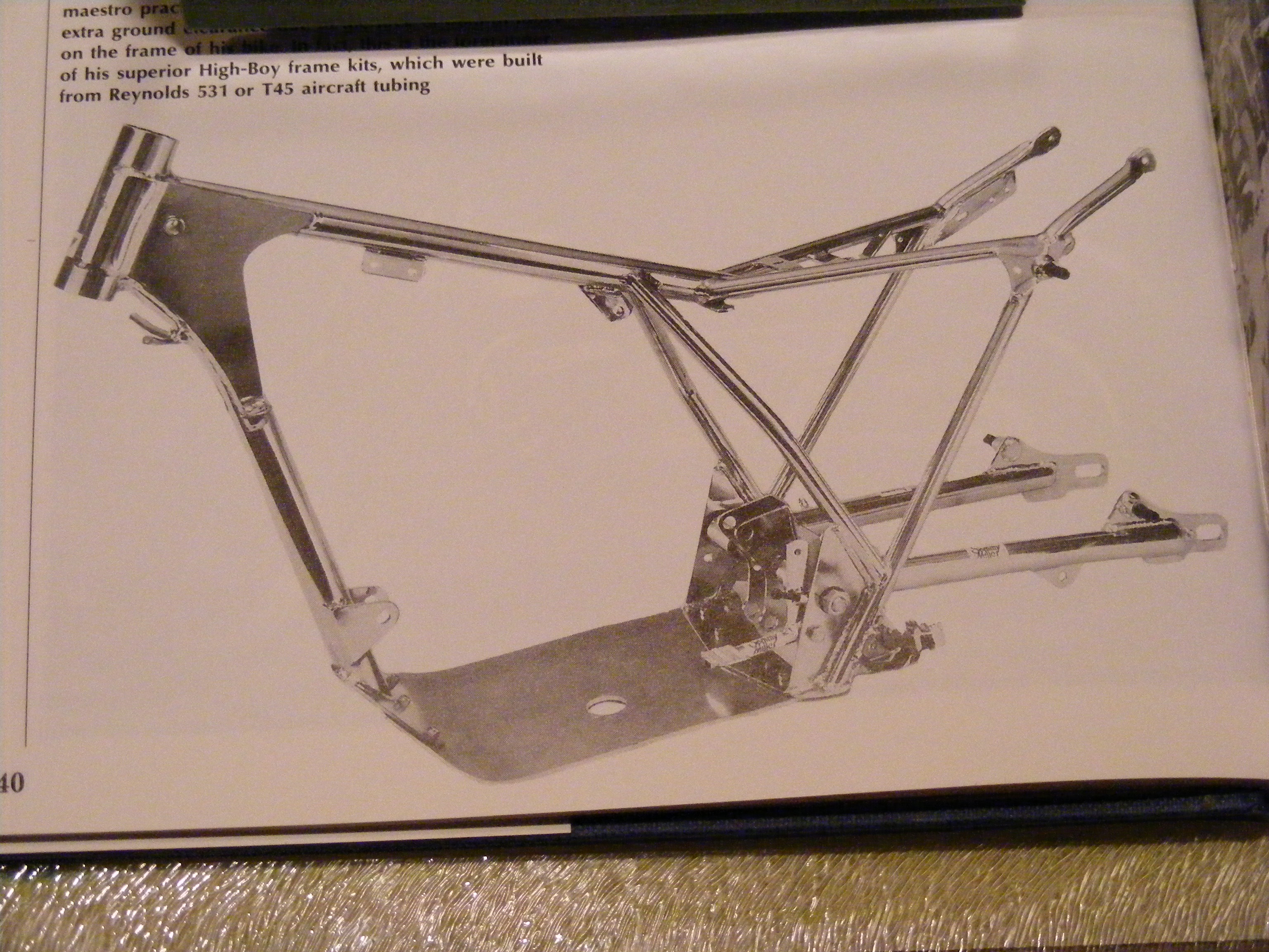
The frame-mounted tank is a chain oiler :-
(extract from 1973 SM catalogue)
Later Sherpa models incorporated a chain oiler in the swing-arm tube, from the factory..


.jpg.040072227964d5228780269f9c9fb788.jpg)
85007.jpg.2671620f9101af094c9b368a357c6775.jpg)
Bultaco Tank No1, ID Please
in Bultaco
Posted
Yes, late model Sherpa. You may find a date on the underside, at the rear.
Here's a NOS one in my collection :