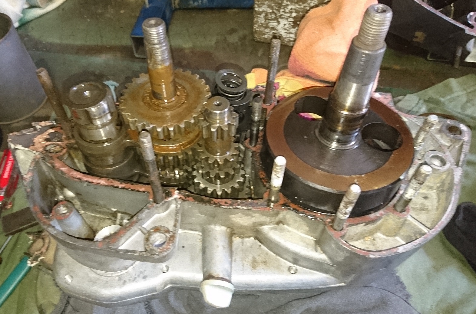
Finally finished the engine/gearbox rebuild and fitted back to the frame this evening. Also took some pictures of the remains of the steel clutch follower I replaced - shows what happens when you run steel on steel without oil - or not enough oil.
Now have to rebuild the exhaust system and tank unit, then all the fiddly bits.
That's a great method,in reality mine will be just hard graft ,the last crappy paintjob on the motor is failing off anyway,around the fins on barrel and head will be the hardest I feel.
I tried many options to clean the fins, but couldn't get into the main part of the casting well enough and the white corrosion just didn't want to cooperate enough. The hydro-blast took all the corrosion, mud and 99% of the paint off back to bare metal - I was tempted to leave it plain, but that wouldn't be original. Engine finally going back together now.
Thanks again,engine will be essentially stripped of paint before repainting,well versed with this being a car restorer and aircooled guy,honestly I wouldn't be bothering with these but as its engine out to repair the frame it makes little sense not to,besides I 'am thinking the frame is worse than it looks....really.
Cheers Dean.
I got the head and barrel hydro-blasted to get rid of the years of mud, paint, corrosion and more paint so I could work on the new head studs without getting covered in crap, then gave them a coat of hi-temp matt black - looks nice now.
Any paint on the engine will make it run hotter. Keep that in mind
Kirchoff's laws of radiation make it evident that aBLACKbody is not only a perfect ABSORBER but also a PERFECT EMITTER ofheat. Hence ablackcylinder will cool down faster than a natural finish one.
I need to fix the frame in more ways than one .....horrible past owner repairs
You'll get there, just keep doing a little at a time. On the 247 the rear shocks are held by circlips, I found I could tap the mounts M8 and used button head cap screws - no chance of a circlip coming off now,
Remove swingarm today to sort previous cock-ups done in the past,its a real mess as is the frame.
Welcome to my world. Currently working through the power unit, surprisingly only a few "modifications" to correct. My exhaust system still to be tackled, good hints above for me.
manual says 2.7mm BTDC is that when the points are fully open or do you set with points just open @ 1.8mm???
On every other brand of engine I know, the measurement is only accurate when the points just open - so I interpret that as spark to fire at 2.7mm BTDC. They also specify points gap as a range, so points at the wide setting will fire slightly ahead of points at the narrow setting. In those engines where you "can't" adjust the timing, you can often get =/- about 2 degrees by points adjustment and still be in range. It's all smoke and mirrors, lol.
Edit.... have googled chainsaw decomp valves and appears they are a fairly small thread,appears 9mm and 10mm are common,I will most likely use an old 14mm sparkplug and make an adaptor,will visit local small engine place tomorrow,will update .
Might want to check out Royal Enfield decompression valve on eBay, might save you some work and $$
Case repairs completed, new bearings and seals fitted, kick start clearance and timing set and the two engine cases now back together - progress!!!
If anyone is interested, the assembly order for the kick start mechanism inside the engine cases is as follows - kick lever side spacer is 1mm, then the circlip, another 1mm to 1.5mm spacer goes between the circlip and ratchet spring (this spacer not shown in parts diagram), ratchet spring, small ratchet part, large ratchet part, 4mm spacer against bush.
If anyone wants to know how to set the kick start timing to get the best out of it, please let me know. It's a little involved to explain, but I'm happy to try if needed.
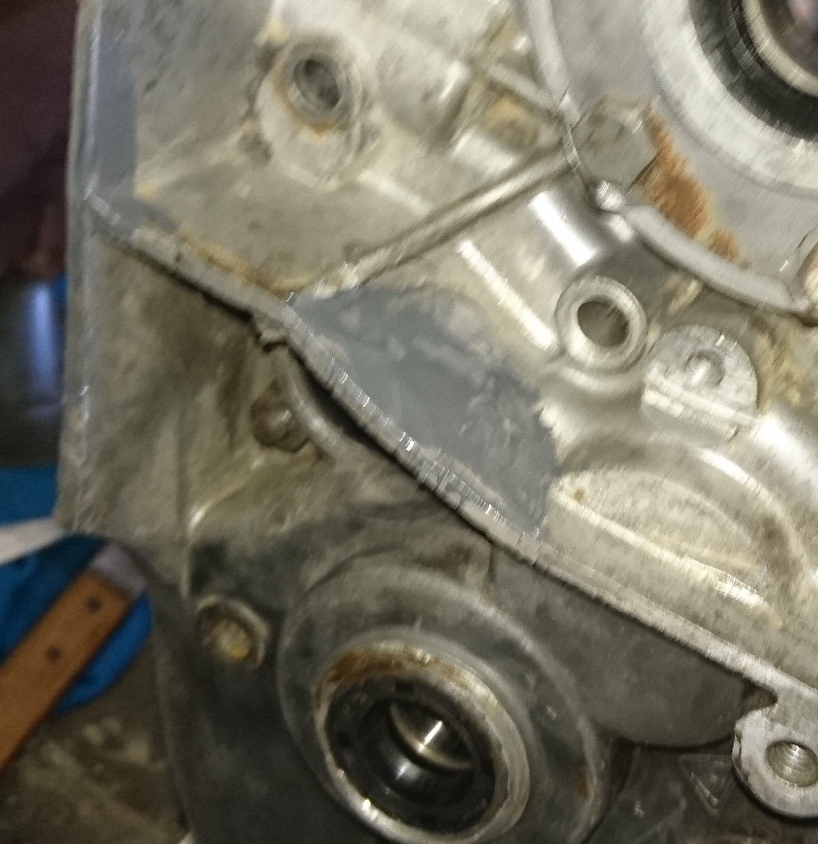
Got some more done over the last couple days. Completed the kick start settings/clearances and timing, repaired the case damage from kick start over-travel and tidied up where the chain had hacked the side of the case, fitted the new seals and bearings, modified the oil drain and assembled the two engine halves. I was pleasantly surprised how easy it was to reassemble.
When the kick start timing is correct and the lever is in the right place, the mechanism is quite good and it becomes difficult to over travel the shaft and cause the damage - there's even enough room to get a thin metal plate on the side of the damaged casing web. Pictures show the aluminium patch on the kick side and the JB Weld on the flywheel side. I veed both sides of the hole in the case web, screwed the patch in place, then completely filled the hole made by the kick start shaft stop. Now when the timing cover and gasket goes back on there shouldn't be any water ingress into the magneto.
Does anyone have a wiring diagram for the ignition on one of these? I won't be running lights, so only need the ignition circuit.
Well, hopefully we learn as we go, it would have been wonderful to have an assembly type manual to refer to, instead of only having a parts sketch/diagram. Having put the kick start mechanism together and apart and the engine case on and off so many times, I've finally worked out what it's all about.
I made the new inner bush from high quality brass with an oil gallery as opposed to the oillite original type. The spigot end of the shaft only goes part way into this bush and repeated kicking will potentially/eventually cause it to fail.
The whole mechanism relies on the ratchet to disengage when the lever is in the "park" or "home" position and that's controlled by the timing of the outer section of the ratchet (4365.011) and the small guide (0265.10401). The full depth of cam on the ratchet must be behind the guide when the kick start lever is in the park or home position, and start to travel down the cam ramp immediately as the lever is pushed down. Failure to get this right won't allow the ratchet to catch on the gear section (2265.00103) early enough to give a full length kick and could allow a partial contact in the ratchet - that and/or poor spring pressure maybe why the kick start fails on some of these.
Once I've got the timing and assembly 100% including the .5mm thickness of the centre gasket, I'll measure the end spacers and post here - it might save someone else some headaches.
New bearings, seals and gaskets arrived from InMotion, so better get the case repairs finished and now really looking forwards to reassembly.
Thanks, but it's already got that fitted. Water lying in casing was dirty (muddy coloured).
Have you figured out how/where the water got in there yet? I wouldn't be drilling the drain hole unless there's no way to stop the water getting in there in the first place. I had a drain hole (with cotter pin) in the tractor clutch housing and it does work, but then I didn't drive it through streams or other deep water very often.
If the PO didn't have a breather tube fitted and plunged a hot bike into a cold stream, water could get in through the breather, through a non-sealed cover gasket or cracks in the cover or through damage caused by kick start over travel. Can't see any other way muddy water could get in there.
Do bear in mind there is a requirement to shim endfloat albeit within fairly loose limits. I have a few spare engines in bits but they also are missing all the useful spacers and shims.Sorry this isn't much real help.
But be assured many of us share your pain
Thanks for letting me know that many of us share the same problem, lol.
I've decided half to one mm end float has to be better than 4mm and having the spigot go 3/4 into the bush has to be better than half way. By using a thinner spigot end spacer of 1.25 instead of 4.25 it's allowed the kick start gear to line up with full tooth contact, so should also be better/stronger. Fitting a 3mm spacer to the lever end of the shaft (still inside the cases) has reduced the end float to around 1/2 to 1mm with gasket in place.
Only downside to the new shaft bushes is when I temporarily put the timing cover on, the kick start shaft binds slightly on one side of the hole. Still waiting on other bearings and seals so I'll look more into this when the engine goes back together - I'm suspecting the end of the kick start shaft may have a slight bend so need to check it out in more detail.
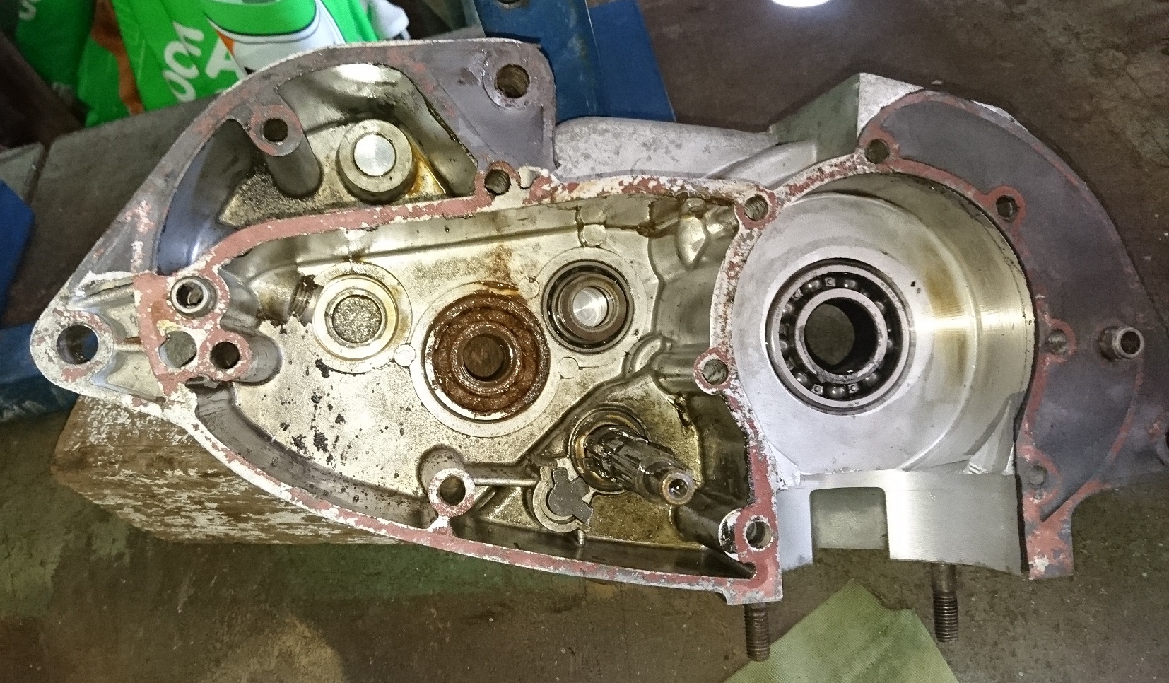
As part of the rebuild on my 247 I had to split the engine cases to replace some bearings, bushes and seals. In the process I noticed the kick start shaft has about 4mm end float. When I looked inside I found the spigot on the inside end of the shaft only goes about halfway into the inner bush and there's a 4mm thick spacer washer on the spigot which prevents the shaft going all the way into the bush. Secondly the starter gear is only partially meshing and looks like it needs to go at least 3mm deeper into mesh. At the other end of the shaft there's a circlip to hold the ratchet mechanism, but no thrust washer between the circlip and the bush. All this suggests to me there should be a spacer washer on each end - about 1.5mm thick on the spigot end and about 3mm thick on the lever end. This would eliminate the end float, set the spigot deeper into the inner bush, line up the gears and prevent the circlip bearing against the lever end bush.
When I look at the parts manual it shows 2165.115 as the spigot end spacer and 0265.118 as the lever end spacer. Mine doesn't have the lever end spacer washer and the spigot end spacer is 4mm thick.
Does anyone know what thickness the spacers are supposed to be? TIA
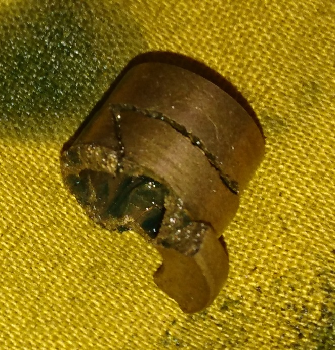
I sure hope you're right :-) Did some measuring and seems all the kick-start shaft bushes and seals will have to be replaced - also need to figure out what's going on with the kick-start mechanism - at the moment it looks like the shaft has been only going part way into the inner bush when the spring should allow the ratchet to slide on the shaft instead of the shaft sliding in/out - this added to the play in the middle bush has caused the inner bush to fail.
At least I found the missing bits of the bush, some of it was ground up by the gears and caught in the drain hole and the biggest chunk was jammed into the top of the drain by one of the gears - took some getting out. In case anyone is interested, the drain hole in the bottom of the case is only about 8mm, then opens up to about 12mm where the plug is - no idea why it wouldn't be 12mm all the way through - it will be when it goes back together. Picture of the remains of the inner bush below.
Good progress, you need the ride to be "soft" compared to a trail bike, you just have to figure out how soft actually works for you at your weight - need to allow the wheel to easily follow whatever you're riding over - too hard in the forks and/or with higher tyre pressure and rocks will tend to skid out in front instead of going under the wheel - I'm sure you'll figure it out once you do a few sections on it.
There are several different valve arrangements in the fork nuts, some of the 247's (like mine) have a spring loaded ball relief built into the nut - when the oil is aerated and forks suddenly compress, you can end up with a face full of oily mist if you don't have some sort of deflector on there - some have a valve like a tyre valve and these don't squirt like the others. I would be wary of adding positive air pressure through these type valves as the only exit under pressure would be past the fork seals. I've seen bikes where the valves have been shut off and the owner/rider accepts a certain amount of oil leakage past the tube seals. Make sure you do your homework is all I'm saying.
Got the clutch cover back from welding yesterday, they did a nice job, shouldn't leak oil when it goes back together.
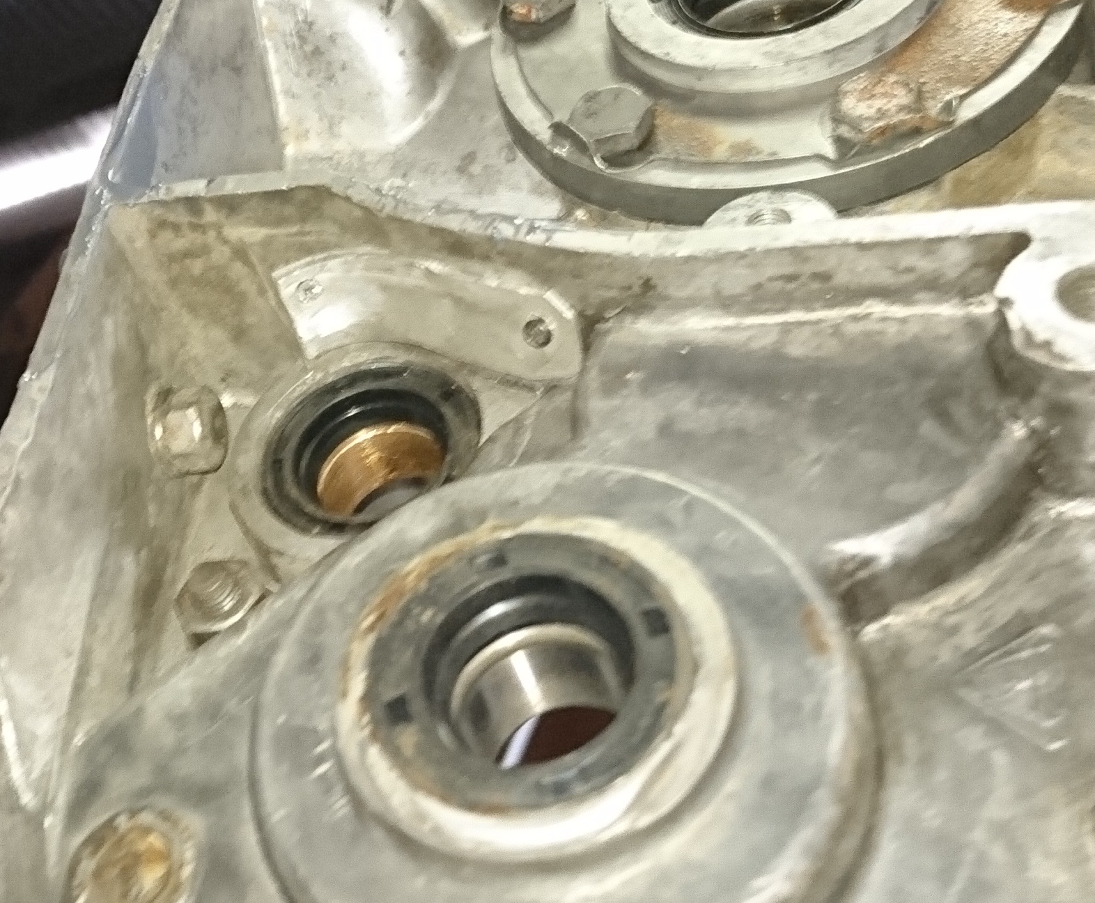
Finished off and installed the 2 new head studs to replace PO's M12 cap screws and started tearing down the bottom end. Finally found the cause of the slack in the final drive shaft - the bearing is full of rusty water, probably trapped in there from when the bike was lying on it side all those years. Another "interesting" one is the inner bronze bush for the kick-start shaft is missing about three quarters of the flange, but so far no sign of bronze bits in the gear case, so unsure what's going on there.
Looks like I'll have to fully strip the bottom end and try to find the missing bits of the bush, then make a new one. Will replace crank seals while I'm at it, so progress will be slow for a while. New final drive shaft bearing and seal on the way from InMotion.
Thanks wobbler, I wasn't trying to be a smart***, I genuinely wanted to know and appreciate your feedback. That all makes sense, especially with the modified foot pegs.
Did you stand the forks up a bit more vertical with the modified yokes? I had a couple of Velo's many years ago, one was better on the road than the other, but the second one was more manoeuvrable in the bush and the only real difference was the front fork angle.
Thanks oldaz,stripped down forks found atf in on leg and gearoil in the other .........jeez what is it with people???,forks generally good condition,talked to the last owner who did little but store it for 15yrs after purchase and he said he had little history on the bike,think the previous owners had been good with exception.
The oil in the forks was mud,lots of ***** in all parts so after a goos clean up and new I should be golden.
Happy with progress so far as no hurry till leg heals,mates son give me some riding boots ,a little worn out but still useable for my needs.
Cheers Dean.
Good job potto, yes you certainly wonder about what the previous people were thinking with some of the stuff you find. Mud seems to be one of the things you find in forks that haven't been serviced - as well as just about everywhere else. When you put it back together it might take some experimenting with different weight (viscosity) oil to get it to suit you. I haven't ridden mine yet, so starting with atf, if I find it's too soft, I'll replace with a heavier grade. Good you got some boots :-)
Thanks wobbler. After all the effort, do you think there's a noticeable difference in the performance?
I notice with this bash plate modification it puts extra tension on the engine and mounts. The plate is curved, so flexible and relies on the strength of only 2 engine mounts.
Does moving the foot pegs back and down a small amount really make a difference and if so, how??
Ok long story short the bike kicked back and wreaked my leg,70mm by 15mm tear in my lower leg,as you may understand its a mess,I made a mistake in starting the bike and its my fault ,bike got some words thrown at it,nevermind lesson learnt...as a wise man said you only stop learning when you die.
My main question is kickstart lever position?????,currently it is about 1130 as the clock go's when in the start /kickdown position is locked in ?
I'am going to look @ the timing and points however after I got it started first after a very long time it cracked up and run good,,anyone got a 1st o 2nd kickstart setup for the starting? ,remembering I need a healed leg and the correct footwear.
Many thanks Dean.
Far as I know the kickstart position sounds about right at 11.30 locked in - kick it over until you get compression then ease it just past with the de-compressor, release decomp and give it a boot and it should start (if it's primed and ready) - make sure you wear boots. Had a RT360 Yam many years ago that would rip your shin out every time if you didn't have good boots and follow correct procedure.
After all the feedback and pictures I've started making the new bash plate. Looking at the trashed side cases on my bike and the Renthal one, I understand why they designed it like that, simply to protect the leading edges of the magneto and clutch cases without compromising ground clearance - they obviously weren't concerned about damage to the lower frame tubes. I can also understand that as these bikes were built to do a task and longevity wasn't in the original plans.
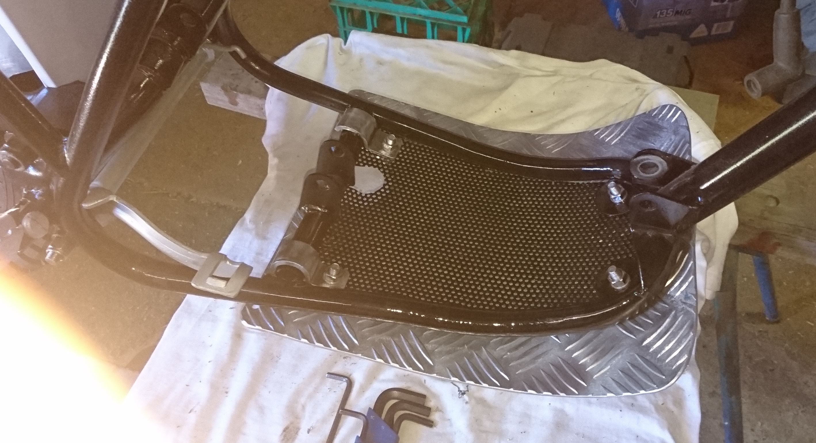
I decided to go similar to the bottom picture keychange posted, except I'm making the back edge a bit longer to go under the rear cross-member. I had some 4mm diamond plate aluminium left from a previous job, so using a piece of that, the diamond pattern will be topside as I didn't want anything underneath that could snag on a log or rock and it won't make any difference on the topside. Still have to figure how I'll attach it and will post a picture when it's fitted to the frame.
Picture of new bash plate below - I built it as I said above - looks pretty with the diamond pattern on top and is nice and smooth on the underneath "contact" surface. Got it shaped up pretty close, then fitted it and "massaged" it to be a neat fit to the bottom rails - may have to massage the edges a little more when the engine goes back in, but happy enough with it as it is for now.


Montesa Cota 247
in Montesa
Posted
Finally finished the engine/gearbox rebuild and fitted back to the frame this evening. Also took some pictures of the remains of the steel clutch follower I replaced - shows what happens when you run steel on steel without oil - or not enough oil.
Now have to rebuild the exhaust system and tank unit, then all the fiddly bits.