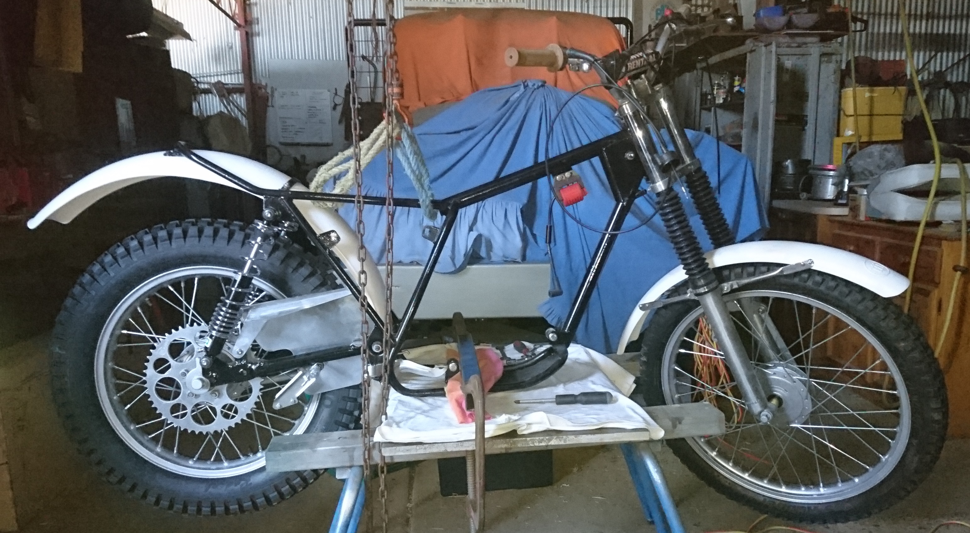
Bash plate made and fitted, (picture below) details are in a separate post, it came out OK, so that's the end of the "frame" work.
In process of stripping engine further. The barrel and head are back from hydro-blasting, a bit more tidying up and finish the new head studs and it will be ready for some engine enamel.
New flywheel puller arrived, so started into pulling the magneto flywheel - no joy for 2 days - soaked in penetrant, applied heat, still no go. Got more serious with it today, more heat while under pressure to the point where I've probably compromised the crank seal on this side, tried impact gun, still no go, breaker bar on the puller and promptly sheered off the M12 bolt in the new puller - more heat and more penetrant while I repaired the puller with a new hi-tensile M12 set screw, got back into it and lay the engine on it's side on the steel bench so it was supported on the crank weight on the clutch side - a good belt with the 4 pounder and it popped - FINALLY!!!
One problem cropping up with our old bikes is that the sliders can develop enough wear to cause the tube to move about too much (radially) in the slider for the seal to work properly. Modern forks have replaceable bushings in the sliders but the old bikes don't have this. If the play is causing problems, they can be machined out to take a sleeve or maybe replaced with less-worn second hand sliders.
The sliders are easy enough to machine if you have access to a reasonable lathe - the outside where the gaiters go is concentric with the bore, so easy to set up - then press in a suitable piece of brass tubing and ream/machine to size. Any competent machine shop should be able to do it.
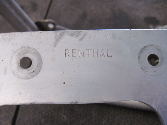
After all the feedback and pictures I've started making the new bash plate. Looking at the trashed side cases on my bike and the Renthal one, I understand why they designed it like that, simply to protect the leading edges of the magneto and clutch cases without compromising ground clearance - they obviously weren't concerned about damage to the lower frame tubes. I can also understand that as these bikes were built to do a task and longevity wasn't in the original plans.
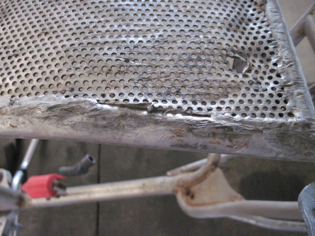
I decided to go similar to the bottom picture keychange posted, except I'm making the back edge a bit longer to go under the rear cross-member. I had some 4mm diamond plate aluminium left from a previous job, so using a piece of that, the diamond pattern will be topside as I didn't want anything underneath that could snag on a log or rock and it won't make any difference on the topside. Still have to figure how I'll attach it and will post a picture when it's fitted to the frame.
Hi, my husband recently bought a 349 and relocated the condenser to under the tank. Seem to have an issue with water ingress to the magneto area after riding burn sections at a recent trial.
He's sealed the magneto casing using instant gasket but water still managed to get in.
Thinking of just drilling a hole at the bottom of the casing to let the water escape. Any comments or suggestions would be appreciated.
Cheers, Fiona
On 247's you often find the inside of the casing damaged from the kick-starter over travel allowing water to get in, might be worth having a look.
They weren't. This one had been hootched up sometime in it's life with a nickel plated frame and swingarm, the Renthal plate, MX shocks, mystery bars, etc. The frame wasn't prepped correctly for the nickel plating, resulting in a shabby crepe finish and corroding when it was left outside for years beside one of the previous owner's house. The swingarm still looks good, but the frame needs to be redone. What the heck, it'll be one of the nicest looking users I've ever assembled.
BTW, yours is coming along nicely!
It would be a pretty looking bike like that, all sparkling with a dash of red, you would be tempted to spend a lot of time cleaning/polishing though.
The bottom rails on my 247 show lots of rock scarring as well (big shock).
I'll most likely just run this period-correct plate on the bike, unless I really get jazzed up about modding it. For now, footpeg mods and having the frame re-nickled are the starting points to reassembly.
Bottom scarring on mine is as bad or worse, so while the engine is out I will form up the 5mm aluminium plate that's going underneath - I figure a loss of 5mm ground clearance isn't going to affect much for me. I've already panel beaten the bottom as good as I can get it even though there's still some bends and scarps that aren't supposed to be there.
I wasn't aware of any of these frames being "nickled" from the factory.
I was under the impression that the frame had been modified for the plate. I scabbed the pics to get a guide on the footpeg mod. Wobbler doesn't seem to post anymore, and has not responded to my PM last October inquiring about the bike. Heck, one of my teammates (heavily) modified a TY80 frame to accept a DT100 engine, and did a similar mod to the lower frame for his bashplate.
That's certainly possible, although I'm not sure why you would go to that much trouble on what many regard as a "weak" frame. Removing the bottom rails wouldn't do much to stop the head piece cracking so many of these end up with. I noticed some of the later bikes use a similar system, but the plate is mounted a lot more securely - don't know if they suffer the same frame cracking.
We used Triumph forks like those in rigid Velo's in the '60's, just changed the oil to suit rider weight. The higher viscosity oil made for a firmer shock for heavier riders, hardest thing was getting the valving right for the lightweight folk.
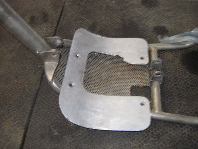
Thanks Brewtus, but the 247C obviously uses a different lower frame. The bash plate in your pictures takes the place of the lower frame rails in the earlier frames. Those lower rails and plate on my frame are badly scored from rock damage, so I'll fit a similar shaped plate under the frame rails.
Fourex says the saddle type clamps are a pain, but at the moment I don't envisage taking the plate off very often - if it turns out the plate has to come off regularly I'll no doubt do something to make it easy.
Thanks for all the input on this, now I know which way to go.
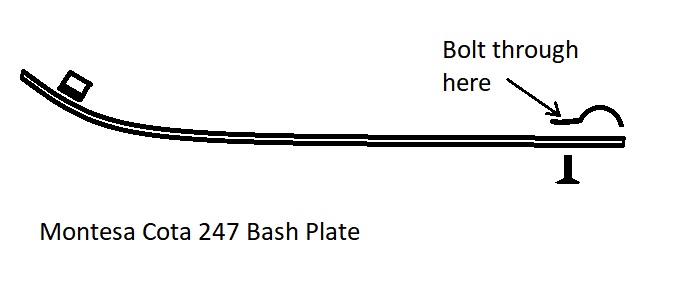
Hi Fourex, I don't think you need to go so far as to weld bits in. My plan is to cut to size, then bend up the aluminium plate similar to what's in Keychange's last picture, except to make it a little longer so it goes to the cross-member at the rear of the existing perforated piece. I'll use 2 half clamps over the cross-member at the back and one each side at the front held by countersunk hex screws (sketch below) - simple but effective.
Thanks for posting the article - I already made the aluminium chain guard, didn't think I would need an extra rim lock (unless I get way more serious), Aluminium bash plate in progress and steering lock puts the inside fork tube at right angles to the head stock on full lock - if that makes sense.
Wheels all rebuilt, new tyres, tubes, bands, rim-locks, brake shoes modified and fitted, made new spacer to replace the knackered speedo drive and fitted the wheels to frame, the fitted up the brake levers, etc - all fixings are stainless steel, even inside the plates. I'm very pleased with the way it's coming together.
I have a MH 200 ( orange) and the yokes hold the forks apart at approx. 120mm which does not leave a lot of clearance for tyre. I also have a 249 and they are 150mm. So do I get a different set of yokes then make new spacers for front wheel ( conical hub ) or leave as is. Some one out there has got to have an answer.
How did the they cope with lack of clearance in the 80s.
Why do you feel the need for more clearance? It's not like you want to fit fat tyres?? I figure if the wheel gets bent enough to hit things, you won't be riding it like that anyway.
A little more progress, finally got the wheels back, they did a great job, hydro-blasted all the alloy, new gal spokes with phosphor-bronze nipples and the rear hub machined and new bearings fitted. I completed the modifications to allow the after-market brake shoes to fit, made new spacer for front wheel now there's no speedo, fitted the new tyres, tubes, bands, rim locks and got the wheels mounted in the frame. It's starting to look like a bike again.
Got the barrel and head are away for hydro-blasting, made a start on the new head studs to replace the M12 cap screws PO put in there, new gaskets and flywheel puller on the way from Inmotion, should get here in a week or two, meantime I can finish off the brake connections and other detail bits, then get back into the power unit.
Nice idea but I have looked at this option and the only oil seal I can find at the moment is 7/8" ID x 11/4" OD x 1/4" wide. Unfortunately that won't leave enough material around the kick start spigot casting at either end!
It's a bit of a shame as I was going to buy a cheap boring head for my mill to machine the recess!
I need to check if the cover will fit on my lathe face plate this evening. If I can, I may be able to design a spring plate retainer and combined oil seal assembly to fit in a recess machined into the outer end on my lathe.
Bruce.
Don't rely solely on imperial measurement seals, I've found quite often you can get a metric seal that will do the job and solve a problem that's been around for many years. I'm guessing you've already looked at machining the outside of the boss off and replacing it with a bolt on unit incorporating a seal, otherwise I hope it fits on your face plate.
Hi all new to forum and to trials recently acquired a montesa 315r 1999 currently stripped down for rebuild but in need of piston and rings I know the oem rings are discontinued and that where I need help what are my options going forward any knowledge infomation greatly appreciated.
Thanks in advance
Just a simple question, why not machine the piston to accept a commonly available ring-set? In Australia we have many places where you can buy rings to suit all sorts of applications, so as long as you can find some of suitable diameter, you can usually get the ring grooves machined to suit - or am I missing something??
Always fun to discover your new purchase was once owned by a butcher, and even more fun reversing the damage done by said butcher. Got my fingers crossed that you have discovered the worst of it.
I always look for the positives and one thing I can be positive about is this has turned into a bigger challenge than I imagined.
After cleaning up the threads, I got the exhaust flange nut to work last night, seems there's enough good thread deep in the barrel that will allow it to work (fingers crossed) and after some measuring I believe I can make some stepped head studs to replace the over-size cap screws. Decided to get the barrel and head hydro-blasted to remove the corrosion and left-over paint, same shop can also weld the clutch case - again, not cheap but I believe necessary. Think this is going to take a while to get it sorted - I did tell myself it would be a summer project :-)
Finally starting to get into the power unit - the further I go, the worse things look. As I said above somewhere, the clutch case is cracked and needs welding, the kick-start stop has punched a hole through to the magneto, chain has come off at some time and chewed up the right side engine case, most of the material that locates the secondary shaft seal is torn off, the drive sprocket has slipped on the secondary shaft at some time and damaged the tapered section, there's excess play in the drive end of the secondary shaft and seal is damaged, cylinder head has been drilled out to accommodate 2 over-size cap screws (other 2 head studs OK), piston is 0.25mm over-size and looks OK in the bore, but can be twisted a bit as though the pin is loose (haven't pulled the barrel yet), both the head and barrel fins have surface corrosion that will have to be treated (maybe hydro-blast) and the exhaust clamp thread is chewed up. I removed and repaired the magneto nut, it had been hammered on a lot, but thread is still OK so that's one positive.
Will pull the barrel next, then split the cases before I decide what to do with it all. Will order a flywheel puller this evening, don't have anything with the right thread to make one from.
The kickstart hole on my 349 is patched with silicone now, I didn't want to risk getting anything hard catching on the flywheel!
I understand, any welding repair requires removing or shielding the flywheel, possibly removing the kickstart shaft and ideally removing and stripping the right side engine case. Once welded any excess metal can be dressed back with a rotary tool and it should be good as new again. Be aware it's also possible to put a suitably shaped steel (or stainless steel) piece over the hole, seal with silicone or gasket cement and rivet or screw in place. Yes it's fiddly, but possible and doesn't require a complete engine strip down. I've also had great success using Devcon F aluminium putty to repair VW crankcases.
A shaped piece of copper to protect the flywheel will also prevent any excess welding material getting in the way and there's still room to get a rotary burr in beside the kickstart shaft, only downsides I can see with this approach is potential heat damage to the kickstart seal and how good the welding operator is.
I already have to strip the engine case to see if the main drive bearing is loose in the case, worn out, or loose on the main drive shaft, so will repair the kickstart damage while it's apart.
Been following with interest your refurbishment of your UKR. I have a mk4b the version before yours and have found similar problems to what you have come across. Your timing cover might have been damaged by the chain but pay particular attention to the inner case around the Kickstarter shaft, in a lot of cases the Kickstarter itself has been positioned to far forward on the splined shaft in the miss belief it would give a longer throw to the kick, unfortunately all it does is allow the stop on the shaft to punch a hole through the inner casing allowing water/moisture into ignition.
The correct position of the kickstart should be the ' one o clock ' or 30 degrees, or looking side on parallel to the frame down tube.
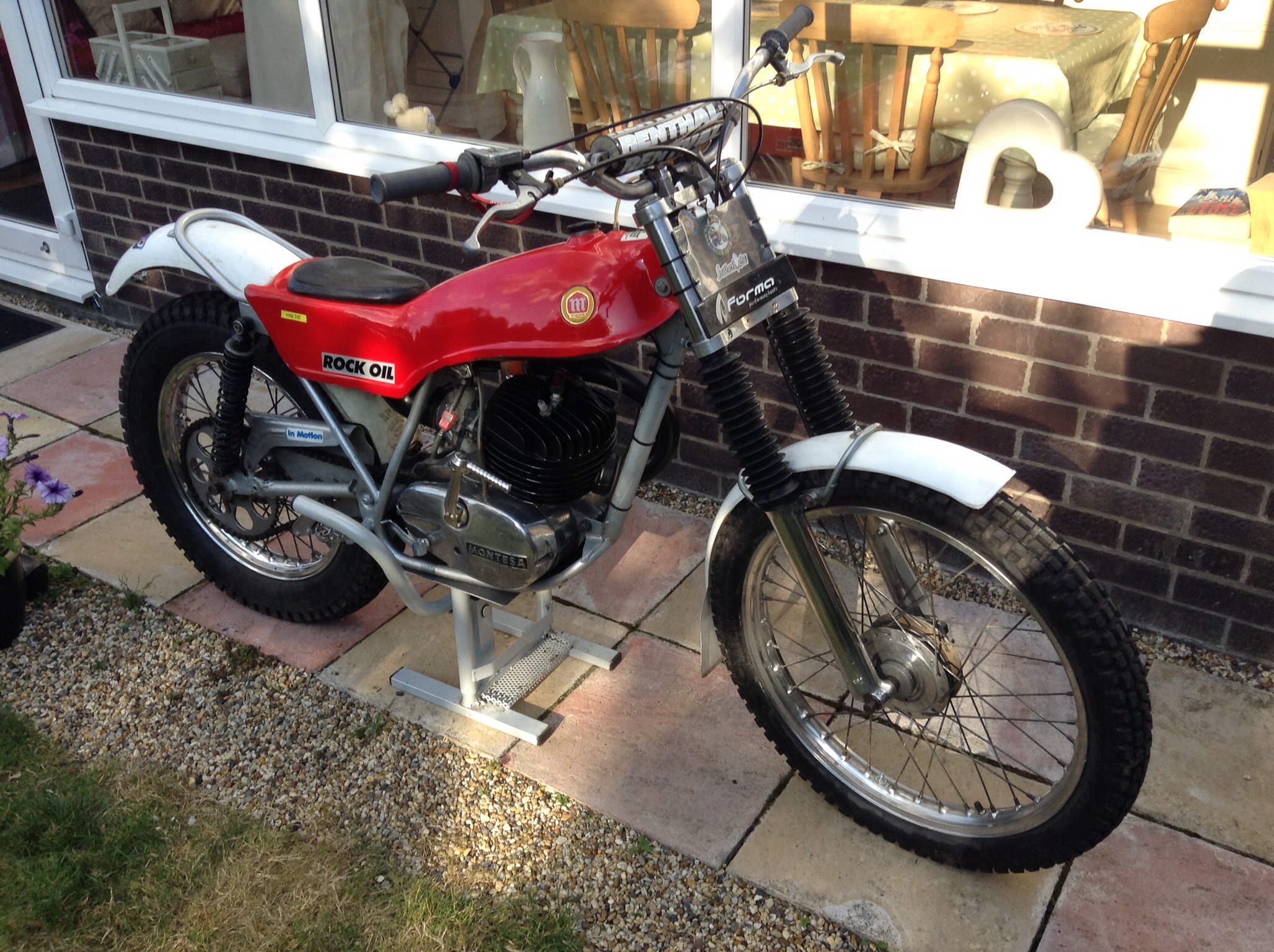
Hope this helps, here's mine.
They're a great looking bike when complete, thanks for sharing. I already know what you mean about the kick-start lever - I've already found the big wad of silicone in the hole. I'll do a better repair than just silicone when I get into the case repairs. The timing cover doesn't appear to be damaged from the chain, it's the side of the engine case where the main drive seal is - still some of the seal retaining boss left there so that's a bonus - just hoping the main drive bearing isn't loose in the case, guess I'll find out soon enough.


")

 Got my fingers crossed that you have discovered the worst of it.
Montesa Cota 247
in Montesa
Posted
Bash plate made and fitted, (picture below) details are in a separate post, it came out OK, so that's the end of the "frame" work.
In process of stripping engine further. The barrel and head are back from hydro-blasting, a bit more tidying up and finish the new head studs and it will be ready for some engine enamel.
New flywheel puller arrived, so started into pulling the magneto flywheel - no joy for 2 days - soaked in penetrant, applied heat, still no go. Got more serious with it today, more heat while under pressure to the point where I've probably compromised the crank seal on this side, tried impact gun, still no go, breaker bar on the puller and promptly sheered off the M12 bolt in the new puller - more heat and more penetrant while I repaired the puller with a new hi-tensile M12 set screw, got back into it and lay the engine on it's side on the steel bench so it was supported on the crank weight on the clutch side - a good belt with the 4 pounder and it popped - FINALLY!!!
Shut down the workshop and quit for the day.