| |
-
Hi bsaweezer,
I had the same problem on my TY250E.
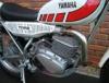
You can make life easier next time (and for tightening up) by filing the end of the damper tube with the two flats into a 12mm hex.
Then use a 12mm impact socket (six sided socket) and long extension to hold the tube while you torque up or loosen of the bolt.
see photo attached.
cheers Rich
-
Hi
If you can't find a code to mix from then the warm whites that were used on Landrover Defenders, and the New BMW mini look pretty close.
regards
Rich
-
update: rolling chassis completed.
Well I finally received the last batch of swing arm parts and completed the bike to a rolling chassis. When initially trying the bike for suspension sag the suspension had almost no sag so I removed the additional 5mm spacers from the forks and set the rear shock circlip into the next to bottom groove. This has given me about 25mm sag front and rear with me standing on the pegs and no engine fitted. The rear suspension seems firm so I don't think the 50lb springs will be needed. The fork rebound damping also definitely feels firmer with the mod.
Here's a pic of the bike, engine is away for new conrod and rebore.
-
Hi Ben,
For your decals have a look at http://classicbikedecals.co.uk/ or http://www.francetrialclassic.com/uk/famille/8/1.html
Matching paint is a nightmare as the accuracy is in the eye of the beholder but take a look at some of the older landrover defender whites, they have some of the creamier shades which are similar to the TY warm white.
regards
Rich
-
Hi Steve,
Thanks for the reply, phoned Talon this morning and they do drill the 288 sprocket to 81 mm bolt centre diameter. My hub is definately 80 mm though. The guy at Talon said they could drill another set of holes at 80 mm BCD in between the original holes at 81mm. Looks like that is the answer for me. Can't believe this is a one off though.
Cheers
Rich
-
Hello All,
Quick question here regarding rear Talon sprocket on a TY250E rear hub. I ordered up a Talon 44 tooth dished sprocket (520 chain) with a reference number of 228. The sprocket seems all ok apart from the bolt holes don't align correctly. The pitch circle diameter of the hub is 80mm but the sprocket is 81mm. The bolt holes are all slightly out of alignment by enough to prevent the threads engaging. The rear hub is stamped 43401, does this mean it is a TY250A part? Was there a difference between the hubs on A and the later models? Anyone come across this before? or have I got a bad sprocket?
Cheers
Rich
-
Well I've taken your advice Mr Feetup and cut down the spacers to 5 mm and moved the stanchions to flush with the top yolk.
The shocks I have are the correct length so just a matter of spring rate. I weigh about 80kg and bought the 40lb spring version after talking to John Cane at TY, and also looked at other sites selling the Betor shock where they were recommending the 50lb spring for 90kg and over riders.
I guess setting the rear sag to match the front will be the test, if the circlip ends up in the top groove it will be spring changing time.
I've always been a follower of the Lotus suspension philosophy - soft springs/stiff dampers - rather than the other way round.
cheers
-
Hi Alan,
I was told that the 13.5" was the standard length shock for my '78 TY so hopefully the bike should sit level. I was a bit wary of the chain rubbing the top of the swing arm or the rear flywheel/sprocket cover mounting boss with the longer shocks. The shocks fitted when I bought it are a couple of inches longer than stock and made the bike look unbalanced. I have spent years riding xc mountain bikes so the low bars are ok for me, and it makes it easier to keep the front end down.
regards
Rich
-
Hi Feetupfun,
Yes, I know the spacers are a bit long, it's all a bit experimental at the moment. I am building the back end up with 13.5" Betor gas shocks and 40 lb springs but haven't had a chance to check the front/rear sag yet as I'm still waiting for the swing arm bush tube to arrive. Once I get to a rolling chassis stage I can set up the sag and hopefully shorten the front spacers a little, at least being nylon it is easy to cut them down if coilbinding is a problem.
Do you have any advice regarding the amount of sag to aim for and the positioning of the stanchions in the yokes? I am running 5 inch rise bars, standard footrests and I'm 6' tall so a fair bit of weight goes over the front end. I was going to run them about 5 mm above the yoke and take it from there. Would be good to know what works well on yours.
Cheers
Rich
-
update on fork mods
I have just got my stanchions back from the chroming shop and built everything back up again. Did a couple of mods to see what I can do with whats already there before going down the cartridge emulator route.
To stiffen up the rebound damping I filled one of the 2 mm holes at the upper end of the damper tube with solder (and filed it flat/smoothed with 1200 wet and dry).
I also filed the small cylindrical projection on top of the damper tube into a 12 mm hexagon, this allowed me to hold it with a 12 mm six sided socket and a long extension when tightening the damper tube bolt.
I have rebuilt the sliders with Allballs racing three lip seals and new dust seals. I have blended 10w fork oil with hypoid gear oil to arrive at an approximate SAE 30 viscosity.
After assembly I filled the fork to 15mm above the damper tube at full extension (spring not fitted). The fork was primed and left to settle to remove air bubbles and the level rechecked. The oil level at full compression is 130mm below the top of the stanchion. I wanted to retain as much air space above the oil as possible to give a little spring assistance.
The coil springs were refitted and 25mm nylon spacers were fitted above the springs to add some preload. Testing the forks on the bench the rebound damping on longer strokes is much more controlled, with short stroke being less affected. the compression damping seems still quite light so hopefully the forks will still respond quickly on the roots and small rocks but be less bouncy on the bigger stuff.
The triple lip seals seem to work very well as there is very little 'stiction' even on a newly rechromed/reground stanchion.
heres some photos I took along the way.
http://i575.photobucket.com/albums/ss194/r...rfulllength.jpg
http://i575.photobucket.com/albums/ss194/r...E/damperhex.jpg
http://i575.photobucket.com/albums/ss194/r...mper2mmhole.jpg
http://i575.photobucket.com/albums/ss194/r...ampersolder.jpg
-
Hi,
I'm not familiar with the sizes of the rose joint on the mono but you might find something suitable here: http://www.ashleypower.co.uk/oilite.htm
I've used some of these in swing arms instead of the fibre bushes and they are very good. Lots of size combinations and a reasonable price too.
cheers
Rich
-
Hi Mark,
I've just bought a pair of Michelin trial comps (both tube type) from Woosters Motorcycle Spares in Leeds for
-
Hi Flymo,
Yes, had a chat with John from TY this week and he is looking to do an alloy airbox replacement as well. Still a way off though so its a DIY job for me at the moment. I guess if lots of people are asking it makes it viable to get these parts reproduced.
cheers
-
Im in the process of building a replacement airbox for my TY250E, so I have bought a standard TY foam filter to get an idea of the size required. I needed to make a new cage for the filter (the wire mesh bit which goes inside the foam to keep it's shape) and had looked at various very expensive sheets of wire mesh down at the local Halfords. Anyway, the answer was staring me in the face (well hanging off a tree actually).
Go down to your local pet shop/wildlife store and have a look at bird feeders. The ones that are just a mesh tube full of peanuts. Yep - you can have a custom made wire tube perfect for the job at a bargain price. And another plus point is you can just put the nuts on the bird table and help reduce bird frustration as a bonus.
cheers!
-
Hi Skippy,
Standard plug is an NGK B-7ES gapped at 0.5-0.6mm.
If you need tech data here is a good source: http://www.cmsnl.com/yamaha-ty250d-1977_mo...%21SERVIC1.html
Regarding the backfiring - is that spitting back through the carb or popping in the exhaust?
cheers
-
Hi Tony
Im tackling my restoration in a different order, got the frame powder coated first and now have a pile of stuff on order. Just got the air filter and sheet of alloy so I guess the air box is now on the agenda.
Had a local guy do my frame in a chrome effect silver, came out really nice - almost looks nickel plated.
He has also done my magnesium castings and they turned out well despite the usual corrosion.
I don't normally build my bikes on the living room carpet by the way, was just a good place for a quick photo!
-
Hi, Just to add to what Dave said. The clutch release mechanism on the Suzuki TS185 is a rack and pinion arrangement. The clutch cable is attached to a lever under the small front cover on the right side. The lever turns a shaft which runs through the clutch cover casting and ends with a small pinion gear. The pinion gear meshes with a short rack gear attached to the clutch pressure plate.
To remove the clutch cover the shaft has to be able to rotate so the pinion can disengage from the rack as you lift the cover away.
Double check that you havent missed any casing screws and a sharp tap with a rubber mallet should break the gasket seal.
Same thing applies when you rebuild, make sure the pinion engages properly with the rack as you fit the clutch casing.
I'd replace the springs along with the plates as they tend to stretch and lose their tension.
best of luck with it
Rich
-
Nice bit of fabrication there Tony, I think you got the maximum capacity for the space available.
-
Hi Tony,
I remember reading somewhere that you should aim for about 1 litre of airbox volume for every 15 bhp the motor produces, can't vouch for this but I guess your airbox must be around that size - especially if you are using the space vacated by the oil tank. Your right about the reed valves - they should 'trap' most of the pressure wave in the intake port, so anything that does make it through will just help to pop the reeds open again when it returns back up the system. Of course a lot of this is academic as a trials engine is not used in the top end of the rev range like a motocrosser or go-kart. Those boost bottles that add volume to the inlet port are doing a similar job - synchronising the resonance in the intake air flow to the opening and closing of the ports. This only really gives a benefit at one engine speed, so the main effect is to shift peak torque to a higher or lower engine speed.
As Feetupfun said earlier, using a good quality air filter foam/oil which does not add too much restriction to air flow, combined with your still air theory to maximise snap throttle response is probably the most important thing for trials use. If you can use a standard OE filter in your airbox you stand more of a chance of the OE jetting being OK.
-
Regarding the air hose, might be an idea to install a small filter in the pipe. I remember that some older cars had a small filter gauze on the end of the pick up pipe in the windshield washer bottle. One of those would do the job nicely.
My TY came minus the original air box and with an open filter cone mounted directly on the carb. In my experience I have never found open filters to be very successful on two strokes as you lose the pulse charging effect. So don't make your air box too 'open'. A hole in the air box slightly larger than the carb choke tube (26mm Diameter) is all thats required. No point making the hole any bigger as the air filter cannot suck in any more air than the carb can flow at full throttle.
The theory is that when the inlet port closes a positive pressure wave travels down the inlet, through the carb and is reflected off the end of the enclosed airbox arriving back at the inlet port as it opens on the next stroke. This helps to push the fresh charge into the crankcase. If your airbox is a similar volume to the original, and uses the same intake pipe from the carb you should not be too far out on the jetting.
I have been looking for an airbox but it looks like I'll end up making one too. I've looked at some of the new go-kart airboxes but they seem too large to fit into the space available.
Good luck with the jetting.
-
Just had a look at my carb and there are three white plastic elbows: two overflows on the side of the throttle slide housing which each have a short pipe that drops vertically and goes through a little bracket cast into the float chamber. And the third one is the one I think you are talking about which aligns with a casting in the carb inlet that leads to what I think is the pilot air or bypass air passage. The manual I have shows the hose for this being routed into the main frame tube opening above the gearbox. All the other crank case breathers are shown routed into the main frame tube as well. Not sure if your 100mm pipe would be long enough to reach that? Looks to me like an air inlet pipe that has to be at atmospheric pressure (not subjected to engine vacuum) and kept away from water/dirt.
There is also a short brass pipe on the bottom of the float chamber which is an overflow, and a brass stub connection at the front on the exhaust side for the autolube pipe (blanked off).
My carb has 493 62 stamped on it.
Hope that helps
-
Hi Kev99, My TY250 is 493-300925 which puts it in the 77/78 D/E range, I suspect your is a few months later. The frame had been painted black but I found red paint under the horn bracket. The fuel tank was white with the square short vertical speed block graphic.
-
Feetupfun: Thanks for the pointer towards the YPP valves.
Looking at the website the valves appear to be an adjustable check valve that controls the oil flow through the damper tube (with the holes drilled larger) on compression hits. I guess the idea is to give you more freedom to increase the oil viscosity to improve the rebound damping without making the fork too stiff under compression.
An interesting idea, food for thought.
-
Dear All,
I know this has been discussed before but hoping for a few tips.
I'm currently 'remanufacturing' a TY250E for mildly competitive fun use and have just spent a day stripping the forks. It all came apart reasonably well (half an hour with an air powered impact gun eventually removed the damper tube bolts).
A bit of careful cutting of slots with a Dremmel got the oil drain screws out and deft use of a centre punch got the old oil seals out. So now I have a collection of parts which seem relatively unworn, but one damper tube was rusty so must have been sitting in water for a while. The stanchions are pitted and will be sent off for straightening /rechroming /grinding etc. The sliders look in good condition as far as the bearing surfaces go and will just get a bit of a cleanup and polish on the outside.
I notice that a lot of people fit the forks from a TY mono to improve things on the front end. I really want to keep the original front forks but try to make them work a bit better while they are apart. What do people consider to be the biggest problem with the original set up?
The springing looks to be standard with progressively wound coils and spacers under the top nuts.
From a quick look at the standard valving arrangments it appears that the original forks have a damper tube attached to the bottom of the slider with a valveless piston located inside the stanchion to create an upper and lower chamber. The damper tube has holes which allow oil to flow between these two chambers as the forks compress/extend. The rebound damping action looks to be controlled by the size of two small holes in the top of the damper tube, whilst compression damping is controlled by the two holes in the damper tube and a spring loaded check valve in the end of the stanchion (located under a circlip) which allows the oil to bypass the damper tube. The check valve has a castellated section, the size of the castellations controlling the oil flow. There will of course be a certain amount of oil bypassing the piston due to bearing tolerances, wear etc.
So the main areas in which 'adjustments' can be simply made would be changing the oil weight and / or changing the size of the two small holes in the top of the damper tube (for rebound damping) and increasing the compression damping by machining the top of the castellated section of the check valve (thereby making the 'gaps in the castle' smaller).
As far as changing the spring rate goes, I weigh about 13 stone (180 lbs) so maybe shortening the spring and lengthening the spacer might be an option.
I suspect that just clearing out all the muck, a thorough clean, and fitting a set of new seals and fresh oil to the correct level will give it a fighting chance.
I did notice that on top of the damper tube was a small projection of 14mm diameter with two flats machined at 12mm AF. Could be possible to adapt a 12mm hex socket to fit the flats and thereby avoid having to use the air gun to loosen and tighten the damper tube bolts.
If anyone has any experiences of getting these forks to work properly I would appreciate any suggestions.
Cheers
Rich
-
Well with a bit more spare time, better measuring gear and making up some 'dummy' main bearings to sit square in the crank cases it appears that I have 0.15 mm (0.006") potential end float between the crank and cases. The workshop manual doesn't give a spec but this seems a bit more like what other people would be comfortable with. The smallest shim listed in the parts fiche is 0.3 mm so I guess the verdict is it all goes back together without a shim.
The main problems I found on dismantling (in case anyone else is stripping their motor and wants to know what to look out for) was as follows:
Magneto rotor woodruff key almost sheared. Clutch release axle (the shaft attached to the lever under the gearbox) had a section of case hardening chipped where it contacts the clutch release push rod. Both gearbox ball bearings totally shot. Crank big end side play excessive. The needle rollers in the transmission initally felt rough but after a thorough clean in the parts bath they seem smooth now so I will put it down to dirt.
A tip for anyone splitting the crank cases is that you can make up a cheap crank extractor using a Halford's universal hub puller (
|
|