| |
-
Some Bultaco crank assemblies or rather the big end did not always have any shim/ spacers/ thrust washers fitted but relied upon the con-rod being held central in the bore by the little end /piston spacers doing that job. Montesa used a similar approach but the set-up process was more fiddly involving selective fit little end spacers between the piston and little end eye. I call it a proper job when both ends are controlled by shims or call them what you will.
-
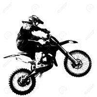
Here goes pictures of old and new con-rods. The hydraulic press, this needs to be powerful enough to start the big end crank pin moving through the flywheel halves. The rest of the pic are self explanatory, old bearing removed, selection of tools and spacers (not all shown). New connecting rod with 20mm dia little end eye. Old piston spacers, new one were stepped to match larger little end burg. Very blocks on surface table (took pics after dti’s used to confirm flywheel alignment. Finished article ??
-
No matter what new trials bikes come onto the market the old ‘original’ bikes have all ‘the character’ that stir emotions and bring back history. Long may you enjoy such an evocative bike??
-
Dam it is it that easy! ?????????????✈️??? ???????
-
I prefer to end up down down
-
Talk to InMotion (Bultaco UK) they know these engines inside out etc. There are about 4 different con-rod and gudgeon pin types. It is important that you get the righ info and spec for your engine. I fitted new con-rod assembly to my M80 which had two bearings on drive side and one on the ignition side. The con-rod had no play up and down and very little sideways but as I was into it I wanted new parts so I knew that all would be good with my crank assembly. You will need a hydraulic press with 40 ton capacity to start the big end shaft moving in the flywheel halves. You will also need to be extremely careful how you do this. I used a few methods to ensure that there was no uneven pressure and to keep the flywheel halves aligned. The new connecting rod and big end bearing together with little end bearing had different diameters to the original but it all went together perfectly. On some Bultaco the little end spacers keep the con rod aligned while on others it is the big end shims that keep the connecting rod ‘in the middle’ aligned. My finished crank assembly has a small end with a larger diameter needle roller bearing but uses the original godgeon pin and two shouldered spacers. The big end bearing has a slightly bigger diameter roller bearing with larger big end eye but obviously the same diameter big end crank pin. Please get in touch with In Motion as they really know their stuff????If you would like I can email you photos of my crank before, during and after fitting new conrod etc. If you go for honing out and oversized rollers don’t forget you will be running on the old crank pin.
-
If it bent without doing damage to the crankcases then heating and bending should be alright, less stress than bending it by kickstarting unsupported.
-
After two years any warranty would have expired, date of sale etc. Or is it that you bought the barrels and fitted one straight away. Pegging or rather pinning the barrel will only be possible if there is sufficient material in both liner and barrel casting. If memory serves me correctly there ought to be a registering lip at the top of the barrel (female) that the liner lip (male) slots into? The cylinder head then traps both when secured in place, so the liner shouldn’t be loose unless there is a gasket/cylinder issue. For the liner to spin there must be significant play some where. How does the other barrel compare? Back to pinning the liner, you might do better to seek the advice of a reputable engineering company/tuner as there is always another solution. Are there any indications that the liner has moved up and down and not just rotated. Hope you get the issue sorted ??
-
Looks to be a very workman like repair, good work. Don’t be tempted to rub down the weld path too much.
-
Identify the type of plastic used for your tank, usually a manufacturers mark and then a series of letters I.e. HDPE etc. Task one find some plastic of the same identification. Obtain a good soldering iron and some degreaser fluid such as brake cleaner. Remove tank, drain fuel completely. Clean out crack area with sharp tool such as a scriber. Use wet and dry paper on the surface area to be repaired. Clean with brake cleaner. Cut strips of plastic from sourced supply about 3-4 mm wide and have a few practice runs with the solder iron heating both the plastic and strip pretty much like welding metal. When you feel confident try the tank. It’s not that hard if you prep everything and get a feel for the method. If you can do this in a well ventilated area don’t breathe in the fumes, plastic welding while holding your breath is no good either. Good luck it’s cheaper than a new tank or paying someone else. Method works fine for me and you can make the repair good and strong by laying up more plastic?By the way petrol will boil before it burns it needs an external spark to initiate burning so your solder iron will not start a fire unless you are careless.
-
Kick start shaft will be slightly bent, check with a straight edge. Clearly mark the bend with a permanent marker pen and familiarise your self with the position. Obtain a length of angle iron, this will be your straightening guide/ jig. Obtain a short piece of flat mild steel bar or similar the same length as the kick start shaft. Set up either a G clamp or mole grips so that you can clamp the flat. This is your jig being readied. Use either ally sheet or mild steel to protect immediate surrounding area as you are going to have to heat the shaft with a gas blow torch or better still oxyacetylene torch. Heat to no more than red hot! Now place the jig on the shaft and clamp together. You may have to do this a few time before you get the shaft straight. This way you place no loading onto the crankcases etc. DO NOT cool the shaft rapidly, allow it to cool by itself in the air. You can clamp gently a pair of mole grips onto the shaft close to the crankcases for use as a heat sink while cooling. BE GENTLE so as not to mark the shaft. There you go kick start shaft straight and no engine strip needed ?? Next time you want to start the engine with the cover off try bump starting the beast.
-
Looked at the Miller offering and then decided I could make my own. Especially when I saw the InMotion tool that was almost identical. Sorted the bits needed from my workshop and just needed to drill 3 holes and bend a 90 degree bend to a piece of mild steel flat bar. Cut a slot in a piece of tube and jobs done, works a treat to??Top tip.....with the clutch apart you can by careful selection of sockets reshape the spring cups and spring top hats as invariably they will be bent. Select a socket that the cup slides into and now select a socket that fits the cup flare by gentle tapping with a hammer the cup flange can be re shaped. The top hat can be dealt with in the same way, I used both 3/8 drive and 1/4 drive sockets and the results for me were very pleasing as the previous owner must have been limited in the skills department?
-
And that nice flat pothole less road was probably paid for by the people who vary rarely see that thing that causes the light☀️?EUr here’s another 30 million??
-
Yep agree totally with you, as can altering the rear upper/lower mount height length. Wheelbase can be changed with the swing arm bend. I reckon there must have been t least three or four swing arms with various flicks at the rear for experimentation. When you are happy with the suspension units that’s when the difference in swing arms comes into play.
-
No movement, but it does look competent. Footrests almost directly under swing arm pivot, ample ground clearance, proper chain guard and the swing arm with its rear bend means some one was playing with steering head angles the easy way!
-
Southern Experts? Three of us drove down from Hertfordshire in firms ex police Range Rover breakdown. It was so wet and hence very muddy but then Mr Miller does like mud!
-
Doesn’t detract from my claim that the CRM was a strong motor?
-
What has to be remembered is that all these Spanish bikes were assembled by hand and this included the hand fettling to make components fit. The frames may have come off a jig but many of the other components were supplied by small one man/woman businesses so fit and quality was down to who ever assembled the bikes. Mr Honda changed all that with a big wake up call called production line acceptance.
-
Well the CRM250 was a very strong 2T, main bearings lubed by gearbox oil if I remember correctly. The final model made well over 30 HP in enduro mode.
-
Like I mentioned you will need to coax the frame and engine together. I find the method I suggested works well by levering the frame gently into alignment with the engine mount holes. Alternatively you can fit the front engine bolts to the frame and either push the engine back towards the rear mounts on the frame or use a ratchet strap. This springing is not unusual and usually can be overcome by careful application of pressure. You may also need to ensure that the bash plate/ sump guard is not bent or twisted. It may also be too long which will require you to bend it at or near to the front radius.
-
Pommyjon I hope that you and your family can accept the condolences of complete strangers, me included, but I wonder where Bultaco would have been if your father had not got involved with modifying the 196cc trail bike! Your father is a part of history and possibly a legend for what he started. Maybe a club would honour your fathers memory and create an award for innovation or some such contribution to trials. To me Tom Ollerton is just as famous as many of the other well known names in this sport.
-
The front two pairs of holes on the curved part should be fitted with countersunk Allen headed bolts M8 and flat washers with nylon nuts. The bolts must not protrude through the nuts by more than 2 threads, apart from weight saving there’s less chance of the bolts puncturing the crankcases. The rear four holes take the same sized bolts again with flat washers and nylon nuts. Don’t tighten any bolts until all are installed, you may need to get someone else to help you as the frame sometimes ‘springs’ especially when the engine is removed. You may not have noticed this when removing engine but the frame can move by up to 5-10 mm. Long rods or Philips screwdrivers can be used insert into frame lugs and enter tip into engine mount lug and gently apply lever force, you’ll get the idea when you start the process. Hope this is of help?
-
Practice first on some similar plastic. The scratches can be gently smoothed by using a Stanley type blade held in the fingers. Protect yourself from cuts tape up the blade so only the knife edge is showing or use a suitable holder. Drag the blade along and over the scratch pretty much like a carpenters plane, in fact a miniature plane is ideal. This scraping action also removes not just the scratch but the faded colour. Wet and dry paper with a bar of soap rubbed onto the paper will help bring back the finish. Aerosol plastic cleaner from a hardware supplier will also help to bring back the finish. Cream cleaner for plastic window frames works really well. I used all of these methods on my 199A Bultaco 350 plastic tank, I also had to plastic weld the underside of the tank on the right side due to the exhaust melting the bottom. I presume that the last owner sat some one on the tank and hey presto instant fuel leak☹️My welding cured it?
-
Seals and bearings from any good reputable supplier look on Google that’s the Simple answer, there’s a clue to a good one?A repair to the barrel will depend upon costs for labour and materials plus parts. Piston and rings etc again Google for more info. Some members on this forum may have been in your position and may offer more useful info. An oversize to 270 cc might be possible but again costs may out weigh the value of a 2007 bike and the cost of repairs. Have you found the reason for the seizure? Hope you get sorted. Don’t forget there are many good dealers that can offer advice, parts and technical help.
-
Hi motovita,
I note you are using longer rear shocks this will quicken up the steering a little which may suit you, or it might be affecting the ride. My 199A had the older and larger air box fitted when I got the bike from Italy, this was a mod carried out to improve torque. In my opinion it gave the engine better breathing as the correct air box could stifle the engine when working hard. The side panels will need to be from the same older bike too. The waterproofing was pants so I set to and made sure that the only way water could get in was if the bike went in above the lower seat line. I may be corrected by more knowledgeable members, but if you look at model 159 onwards you will see the larger side panels. The smaller side panels Inprefer the look of. If you would like to see pics of my 199A with the larger air box and side panels pm me and I’ll see if I can send some to you. ??With regard to the motor cross fork triple clamps this will slow the steering i.e. increase trail which should increase high speed stability not really what you want for trials riding.
|
|